Maytag MGC7430WW Installation Instructions - Page 8
Complete Installation
 |
UPC - 883049184937
View all Maytag MGC7430WW manuals
Add to My Manuals
Save this manual to your list of manuals |
Page 8 highlights
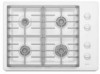
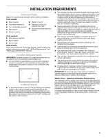
Complete Installation Electronic Ignition System Check Flame Height Adjust the height of surface burner flames. Initial lighting and gas flame adjustments This cooktop is equipped for electronic auto-reignition by means of a spark igniter located at the rear of each burner. The burners are designed to light at any valve rotation that admits sufficient gas flow to support a flame and to automatically relight following a loss of flame due to a draft or other adverse condition. This feature is provided only as a convenience. The surface burner "low" flame should be a steady blue flame approximately ¼" (0.64 cm) high. A Check Operation of Surface Burners Push in and turn the surface burners control knobs to light. The surface burner flame should light within 4 seconds. The first time a surface burner is lighted it may take longer that 4 seconds to light because of air in the gas line. Check the flame on "HIGH" for a blue color. It should be clean and soft in character. No yellow tip, blowing or lifting of flame should occur. Occasional orange flashes are normal and reflect different elements in the air or gas. After verifying the proper burner operation, turn the control knobs to "OFF." If burners do not light properly: ■ Turn surface burner control knob to the "OFF" position. ■ Check that the power supply cord is plugged in and the circuit breaker has not tripped or the fuse blown. ■ Check that the gas shutoff valves are set to the "open" position. ■ Check that burner caps are properly positioned on burner bases. Recheck operation of surface burners. If a burner does not light at this point, contact your dealer or authorized service company for assistance. B A. Low flame B. High flame If the "low" flame needs to be adjusted: This cooktop is shipped from the factory with low and high flame settings adjusted for use with Natural gas. To set for use with LP, the flame can be adjusted using the adjustment screw located underneath the control knob. A B C A. Adjustment screw B. Knob hole (knob removed) C. Control knob 1. Remove the control knob from valve stem. 2. Remove rubber grommet. 3. Use a small flat-blade screwdriver to turn the adjustment screw clockwise until tight. Do not overtighten. 4. Replace rubber grommet and control knob. 5. Repeat for remaining burners. 8
-
 1
1 -
2
-
 3
3 -
 4
4 -
 5
5 -
 6
6 -
 7
7 -
 8
8 -
 9
9 -
 10
10 -
 11
11 -
 12
12 -
 13
13 -
14
-
15
-
16
 |
 |
