Maytag MGD8200FC Instruction Sheet - Page 9
A, B,
 |
View all Maytag MGD8200FC manuals
Add to My Manuals
Save this manual to your list of manuals |
Page 9 highlights
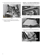
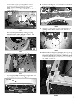
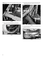
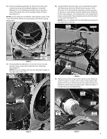
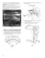
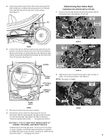
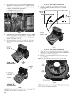
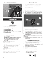
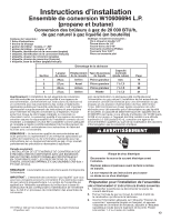
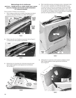
5. Reach around the back of the drive motor and push the idler wheel arm to relieve the spring tension on the belt; then slide the belt off the idler and motor pulleys. See Figure 4. BELT Determining Gas Valve Style CHANGING THE ORIFICE (BOTH STYLES) 1. Remove the two (2) screws securing the burner tube to the burner base. See Figures 1A and 1B. BURNER TUBE IGNITOR GAS VALVE ASSEMBLY FIGURE 4 6. Loosen the top two (2) hex-head screws and remove the bottom two (2) hex-head screws from the front bulkhead. Remove the lower two (2) screws from the blower air duct. Gently remove the bulkhead and blower air duct from the front of the dryer. See Figure 5. (2) SCREWS BURNER TUBE GAS VALVE ASSEMBLY PRESSURE TAP PLUG FIGURE 1A IGNITOR BULKHEAD TOP TWO (2) SCREWS BOTTOM TWO (2) SCREWS LOWER TWO (2) SCREWS PRESSURE TAP PLUG (2) SCREWS FIGURE 1B 2. Slide burner tube forward far enough to gain access to orifice. Do not bump ignitor. See Figure 2. NOTE: The ignitor is fragile. BURNER TUBE BLOWER AIR DUCT FIGURE 5 7. Remove the drum from the dryer cabinet. 8. Disconnect ignitor wires from harness then remove the burner tube by removing the two (2) screws securing it to the burner base. See Figure 1B; then continue to "Determining Gas Valve Style" - "Changing the Orifice." IGNITOR GAS VALVE ASSEMBLY FIGURE 2 SECTION 4 -7 TO 7.5 CUBIC FOOT MODELS WITH 27" CABINET, TOE PANEL, AND REAR CONSOLE Disassemble to access gas valve. To remove the toe panel on some models, a small flat-head screwdriver is required to release the clips at top of panel. Continue to "Determining Gas Valve Style" - "Changing the Orifice." 9
-
 1
1 -
2
-
3
-
 4
4 -
 5
5 -
 6
6 -
 7
7 -
 8
8 -
 9
9 -
 10
10 -
 11
11 -
 12
12 -
 13
13 -
 14
14 -
15
-
16
-
17
-
18
-
19
-
20
-
21
-
22
-
23
-
24
-
25
-
26
-
27
-
28
 |
 |
