Maytag MGDB835DW Installation Guide - Page 9
Install Leveling Legs - installation manual
 |
View all Maytag MGDB835DW manuals
Add to My Manuals
Save this manual to your list of manuals |
Page 9 highlights
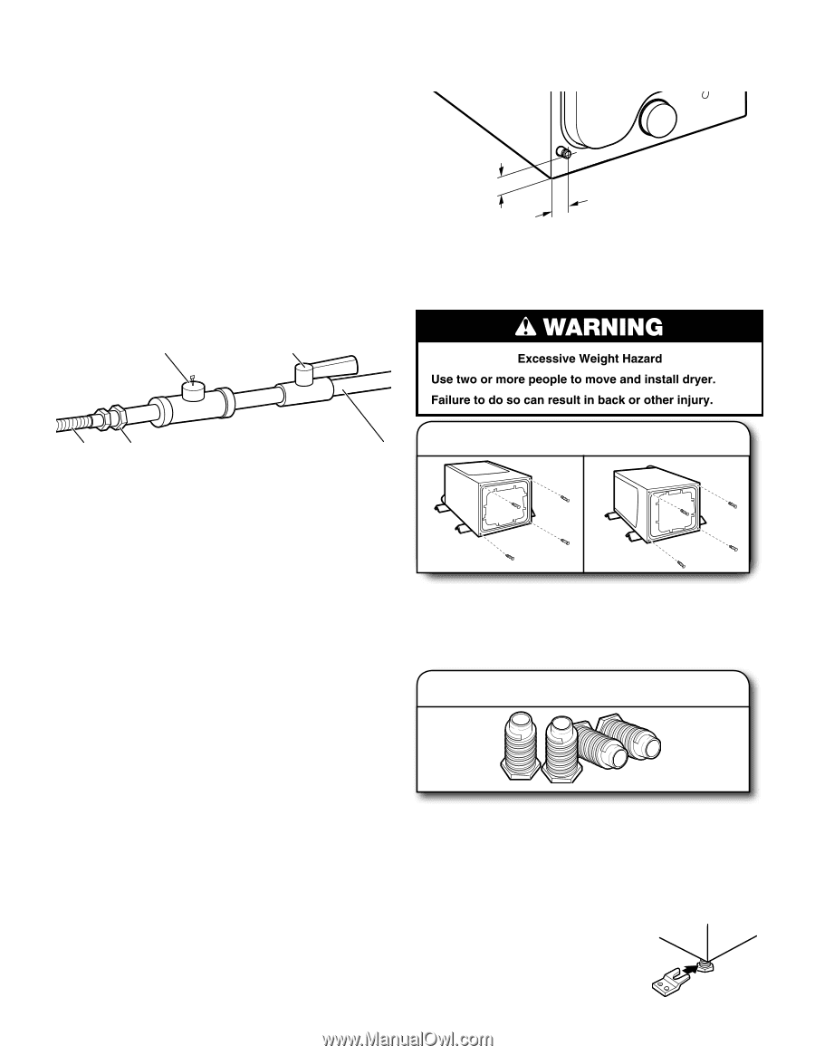
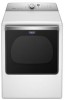
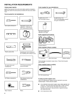
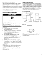
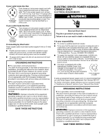
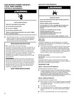
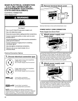
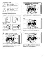
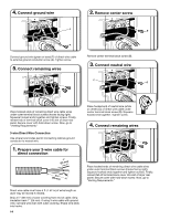
■■ Lengths over 20 ft. (6.1 m) should use larger tubing and a different size adapter fitting. ■■ If your dryer has been converted to use LP gas, 3/8" LP compatible copper tubing can be used. If the total length of the supply line is more than 20 ft. (6.1 m), use larger pipe. NOTE: Pipe-joint compounds that resist the action of LP gas must be used. Do not use TEFLON®† tape. ■■ Must include shut-off valve In the U.S.A.: An individual manual shut-off valve must be installed within six (6) ft. (1.8 m) of the dryer in accordance with the National Fuel Gas Code, ANSI Z223.1. The location should be easy to reach for opening and closing. In Canada: An individual manual shut-off valve must be installed in accordance with the B149.1, Natural Gas and Propane Installation Code. It is recommended that an individual manual shutoff valve be installed within six (6) ft. (1.8 m) of the dryer. The location should be easy to reach for opening and closing. C E DRYER GAS PIPE ■■ The gas pipe that comes out through the rear of your dryer has a 3/8" male pipe thread. 3" (77 mm) 13/8" (35 mm) 3/8" NPT dryer pipe NOTE: For a garage installation, the gas pipe height must be an additional 18" (460 mm) from the floor. Install Leveling Legs A B D 1. Prepare dryer for leveling legs A. 3/8" flexible gas connector B. 3/8" pipe to flare adapter fitting C. 1/8" NPT minimum plugged tapping D. 1/2" NPT gas supply line E. Gas shutoff valve. GAS SUPPLY CONNECTION REQUIREMENTS ■■ Use an elbow and a 3/8" flare x 3/8" NPT adapter fitting between the flexible gas connector and the dryer gas pipe, as needed to avoid kinking. ■■ Use only pipe-joint compound. Do not use TEFLON®† tape. ■■ This dryer must be connected to the gas supply line with a listed flexible gas connector that complies with the standard for connectors for gas appliances, ANSI Z21.24 or CSA 6.10. BURNER INPUT REQUIREMENTS Elevations above 2,000 ft. (610 m): ■■ When installed above 2,000 ft. (610 m) a 4% reduction of the burner Btu rating shown on the model/serial number plate is required for each 1,000 ft. (305 m) increase in elevation. Firmly grasp dryer body (not console panel) and gently lay dryer down on back cardboard corner posts. IMPORTANT: If laying dryer on its back, use the cardboard corner posts the dryer was packed with to avoid damaging the back of the dryer. 2. Screw in leveling legs Gas supply pressure testing ■■ The dryer must be disconnected from the gas supply piping system during pressure testing at pressures greater than 1/2 psi. Using a wrench and tape measure, screw leveling legs into leg holes until bottom of foot is approximately 1/2" (13 mm) from bottom of dryer. Now stand the dryer on its feet. Slide the dryer until it is close to its final location. Leave enough room to connect the exhaust vent. For mobile home use Gas dryers must be securely fastened to the floor. Mobile home installations require a Mobile Home Installation Hold-down Kit. For ordering information please reference the "Use and Care Guide." †®TEFLON is a registered trademark of E.I. Dupont De Nemours and Company. 9
-
 1
1 -
2
-
3
-
 4
4 -
 5
5 -
 6
6 -
 7
7 -
 8
8 -
 9
9 -
 10
10 -
 11
11 -
 12
12 -
 13
13 -
 14
14 -
15
-
16
-
17
-
18
-
19
-
20
-
21
-
22
-
23
-
24
-
25
-
26
-
27
-
28
-
29
-
30
-
31
-
32
-
33
-
34
-
35
-
36
-
37
-
38
-
39
-
40
-
41
-
42
-
43
-
44
 |
 |