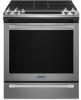
Maytag MGS8800F Installation Instructions - Page 11
Make Gas Connection, Level Range
 |
View all Maytag MGS8800F manuals
Add to My Manuals
Save this manual to your list of manuals |
Page 11 highlights
Level Range 1. Place level on the oven bottom, as indicated in one of the two figures below, depending on the size of the level. Check with the level side to side and front to back. 2. If range is not level, use a wrench or pliers to adjust leveling legs up or down until the range is level. NOTE: Range must be level for satisfactory baking performance and best cleaning results using AquaLift® SelfClean Technology. Make Gas Connection WARNING 3. Use a 15/16" (2.4 cm) combination wrench and an adjustable wrench to attach the flexible connector to the adapters. IMPORTANT: All connections must be wrench-tightened. Do not make connections to the gas regulator too tight. Making the connections too tight may crack the regulator and cause a gas leak. Do not allow the regulator to turn when tightening fittings. A BC D E A. Gas pressure regulator B. Use pipe-joint compound. C. Adapter (must have 1/2" [1.3 cm] male pipe thread) D. Flexible connector HG F E. Manual gas shut-off valve F. 1/2" (1.3 cm) or 3/4" (1.9 cm) gas pipe G. Use pipe-joint compound. H. Adapter Complete Connection 1. Check that the gas pressure regulator shut-off valve is in the "on" position. Explosion Hazard Use a new CSA International approved gas supply line. Install a shut-off valve. Securely tighten all gas connections. If connected to propane, have a qualified person make sure gas pressure does not exceed 14" (36 cm) water column. Examples of a qualified person include: licensed heating personnel, authorized gas company personnel, and authorized service personnel. Failure to do so can result in death, explosion, or fire. This range is factory-set for use with Natural gas. To use this range with Propane gas, see the "Gas Conversions" section before connecting this range to the gas supply. Gas conversions from Natural gas to Propane gas or from Propane gas to Natural gas must be done by a qualified installer. Typical Flexible Connection 1. Apply pipe-joint compound made for use with Propane gas to the smaller thread ends of the flexible connector adapters. See B and G in the following illustration. 2. Attach one adapter to the gas pressure regulator and the other adapter to the gas shut-off valve. Tighten both adapters, being certain not to move or turn the gas pressure regulator. A A. Gas pressure regulator shut-off valve shown in the "on" position 2. Open the manual shut-off valve in the gas supply line. The valve is open when the handle is parallel to the gas pipe. A B A. Closed valve B. Open valve 3. Test all connections by brushing on an approved noncorrosive leak-detection solution. If bubbles appear, a leak is indicated. Correct any leak found. 4. Remove cooktop burner caps and bases from package containing parts. Place the burner bases as indicated by the following illustration for your model: For Models MGS8800F and WEG745H0F: A D C B A. Small (Auxiliary) C. Oval (OV) B. Large (Ultra Rapid) E D. Medium (Semi Rapid) E. Large (Ultra Rapid) 11
-
 1
1 -
2
-
3
-
4
-
5
-
 6
6 -
 7
7 -
 8
8 -
 9
9 -
 10
10 -
 11
11 -
 12
12 -
 13
13 -
 14
14 -
 15
15 -
 16
16 -
17
-
18
-
19
-
20
-
21
-
22
-
23
-
24
-
25
-
26
-
27
-
28
-
29
-
30
-
31
-
32
-
33
-
34
-
35
-
36
-
37
-
38
-
39
-
40
-
41
-
42
-
43
-
44
-
45
-
46
-
47
-
48
 |
 |
