Maytag MOEC6030L Owners Manual - Page 8
INSTALLATION INSTRUCTIONS, REQUIREMENTS, Tools and Parts, Location Requirements
 |
View all Maytag MOEC6030L manuals
Add to My Manuals
Save this manual to your list of manuals |
Page 8 highlights
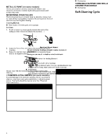
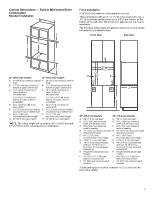
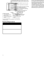
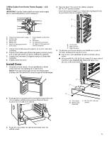
To Steam Clean: 1. Open the oven door of the selected oven and remove all racks and accessories from the oven cavity. 2. Pour 10 oz (295.7 mL) of distilled or filtered water into the oven bottom. Then close the oven door. 3. Touch the Tools keypad. On double-oven models: Select Upper Cavity or Lower Cavity. 4. Select STEAM CLEAN. 5. Select START. 6. After approximately 1 hour, a tone will sound to signal the end of the cycle. Touch the Oven Cancel keypad for single oven models and the Upper/Lower keypad for double oven models to clear the display. 7. When the oven is completely cooled, remove any excess water with a sponge or cloth and wipe down oven interior. If needed, use a non-scratch copper scrubbing pad to remove stubborn soils. INSTALLATION INSTRUCTIONS REQUIREMENTS Tools and Parts Gather the required tools and parts before starting installation. Read and follow the instructions provided with any tools listed here Tools Needed � Phillips screwdriver � Measuring tape � Hand or electric drill (for wall cabinet installations) � 1" (2.5 cm) drill bit (for wall cabinet installations) � Level � Flat-blade screwdriver Parts Supplied � #8-14 x 3/4" (1.9 cm) screws (2) � #8-18 x 3/8" (9.5 mm) Phillips head screws - bottom vent shield (2) � #8-18 x 3/8" (9.5 mm) Phillips head screws - bottom vent trim (2) � #8-18 x 3/8" (9.5 mm) Hex head screws - plastic feet (4) � Rear feet (2) � Front feet (2) � Bottom vent shield � Bottom vent trim Parts Needed � Deflector Kit (on some models) (for ovens installed above warming drawer or for ovens installed using flush installation cabinetry): See the Online Ordering Information section of your Quick Start Guide. Check local codes. Check existing electrical supply. See the "Electrical Requirements" section. It is recommended that all electrical connections be made by a licensed, qualified electrical installer NOTE: Be sure to purchase only whirlpool factory-certified parts and accessories for your appliance. Your installation may require additional parts. To order, refer to the contact information referenced in your Quick Start Guide. Location Requirements IMPORTANT: Observe all governing codes and ordinances. � Cabinet opening dimensions that are shown must be used. Given dimensions provide minimum clearance with oven. � Recessed installation area must provide complete enclosure around the recessed portion of the oven. � Grounded electrical supply is required. See "Electrical Requirements" section. � Electrical supply junction box should be located 3" (7.6 cm) maximum below the support surface when the oven is installed in a wall cabinet. A 1" (2.5 cm) minimum diameter hole should have been drilled in the right rear or left rear corner of the support surface to pass the appliance cable through to the junction box. � Oven support surface must be solid, level and flush with bottom of cabinet cutout. Floor must be able to support a total weight (microwave and built-in oven) of 253 lbs (115 kg) for 27" (68.6 cm) models or 280 lbs (127 kg) for 30" (76.2 cm) models. IMPORTANT: To avoid damage to your cabinets, check with your builder or cabinet supplier to make sure that the materials used will not discolor, delaminate or sustain other damage. This oven has been designed in accordance with the requirements of UL and CSA International and complies with the maximum allowable wood cabinet temperatures of 194°F (90°C). 8
-
 1
1 -
2
-
 3
3 -
 4
4 -
 5
5 -
 6
6 -
 7
7 -
 8
8 -
 9
9 -
 10
10 -
 11
11 -
 12
12 -
 13
13 -
14
-
15
-
16
-
17
-
18
-
19
-
20
-
21
-
22
-
23
-
24
-
25
-
26
-
27
-
28
-
29
-
30
-
31
-
32
-
33
-
34
-
35
-
36
-
37
-
38
-
39
-
40
-
41
-
42
-
43
-
44
-
45
-
46
-
47
-
48
-
49
-
50
-
51
-
52
-
53
-
54
-
55
-
56
 |
 |
