Maytag UXD8636DYS Use & Care Guide - Page 9
Warning
 |
View all Maytag UXD8636DYS manuals
Add to My Manuals
Save this manual to your list of manuals |
Page 9 highlights
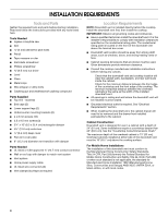
To calculate the length of the system you need, add the equivalent feet (meters) for each vent piece used in the system. Vent Piece 3¹⁄₄" x 10" (8.3 cm x 25.4 cm) Rectangular 3¹⁄₄" x 10" (8.3 cm x 25.4 cm) 5.0 ft 90° elbow (1.5 m) Example Vent System C A B 6 ft (1.8 m) 2 ft (0.6 m) 3¹⁄₄" x 10" (8.3 cm x 25.4 cm) 12.0 ft flat elbow (3.7 m) 3¹⁄₄" x 10" (8.3 cm x 25.4 cm) 0.0 ft wall cap (0.0 m) Vent Piece 45° elbow 6" (15.2 cm) Round 2.5 ft (0.8 m) 90° elbow 5.0 ft (1.5 m) 6" (15.2 cm) wall cap 0.0 ft (0.0 m) 3¹⁄₄" x 10" (8.3 cm x 25.4 cm) 4.5 ft to 6" (15.2 cm) transition (1.4 m) 6" (15.2 cm) to 3¹⁄₄" x 10" 1 ft (8.3 cm x 25.4 cm) transition (0.3 m) 3¹⁄₄" x 10" (8.3 cm x 25.4 cm) 5.0 ft to 6" (15.2 cm) 90° elbow (1.5 m) transition 6" (15.2 cm) to 3¹⁄₄" x 10" 5.0 ft (8.3 cm x 25.4 cm) 90° elbow (1.5 m) transition D A. Blower motor C. 90° elbows B. Transition D. Back draft damper The following example falls within the maximum vent length of 35 ft (8.9 m). 2 - 90° elbow = 10.0 ft (3 m) 1 - wall cap = 0.0 ft (0.0 m) 8 ft (2.4 m) straight = 8.0 ft (2.4 m) Transition = 4.5 ft (1.4 cm) Length of 6" (15.2 cm) or 3¹⁄₄" x 10" = 22.5 ft (6.8 m) (8.3 cm x 25.4 cm) system Install Vent System WARNING Excessive Weight Hazard Use two or more people to move and install downdraft vent. Failure to do so can result in back or other injury. 1. Place cardboard or similar material on top of a flat surface where you can easily assemble the downdraft vent system. 2. Remove parts packages, downdraft vent and blower box from the carton. 3. Remove all shipping materials, tape and film from the downdraft vent and blower box. 4. Install the right and left undercounter mounting brackets to the vent box. Slide the keyhole slots over the guide tabs and push the brackets up to set them into place. B A C D A. Vent box B. Undercounter mounting bracket C. Keyhole slots D. Guide tabs 9
-
 1
1 -
2
-
3
-
 4
4 -
 5
5 -
 6
6 -
 7
7 -
 8
8 -
 9
9 -
 10
10 -
 11
11 -
 12
12 -
 13
13 -
 14
14 -
15
-
16
-
17
-
18
-
19
-
20
-
21
-
22
-
23
-
24
-
25
-
26
-
27
-
28
-
29
-
30
-
31
-
32
-
33
-
34
-
35
-
36
 |
 |
