Meade LX200-ACF 8 inch User Manual - Page 70
Appendix H
 |
View all Meade LX200-ACF 8 inch manuals
Add to My Manuals
Save this manual to your list of manuals |
Page 70 highlights
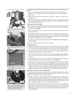
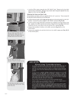
Fig. 60: Back off the adapter ring one full revolution. 12:00 position Fig. 61: Place the microfocuser over the adapter ring. Notice the orientation of the microfocuser. APPENDIX H: DE-ROTATOR AND MICROFOCUSER ASSEMBLY For LX200-ACF Telescopes Equiped with a Zero Image-Shift Microfocuser When using a de-rotator, it is important to attach the microfocuser so that it is backed off slightly from the de-rotator. If the microfocuser is flush against the de-rotator, the assembly will not work properly. This is true also with other accessories that may attach up flush against the de-rotator housing. The diagonal mirror (if used without the microfocuser) may be attached tightly as it does not rub up against the de-rotator housing. To attach the microfocuser to the de-rotator: Refer to Fig. 8, page 14, for an exploded view of the microfocuser assembly. Perform this assembly on a flat surface (such as a desk or a table) before you attach the derotator and microfocuser to the telescope. 1. With the de-rotator on a flat surface, thread on the adapter ring (Fig. 8, B) until it just touches the housing; then back off the adapter ring (i.e., turn it counterclockwise) one full revolution as shown in Fig. 60. 2. Place the microfocuser over the ring with the "hump" of the microfocuser in the 12:00 position as shown in Fig. 61. 3. Using the provided hex key, tighten to a firm feel one of the three microfocuser hex screws (Fig. 8, K) up against the adapter ring as shown in Fig. 62. Take care not to tighten or loosen the adapter ring as you position and tighten the microfocuser in place. 4. Tighten to a firm feel the other two microfocuser hex screws. 5. Attach the de-rotator to the rear cell of the telescope. Fig. 62: Tighten the three microfocuser hex screws to a firm feel. - 70 -
-
 1
1 -
2
-
3
-
4
-
5
-
6
-
7
-
8
-
9
-
10
-
11
-
12
-
13
-
14
-
15
-
16
-
17
-
18
-
19
-
20
-
21
-
22
-
23
-
24
-
25
-
26
-
27
-
28
-
29
-
30
-
31
-
32
-
33
-
34
-
35
-
36
-
37
-
38
-
39
-
40
-
41
-
42
-
43
-
44
-
45
-
46
-
47
-
48
-
49
-
50
-
51
-
52
-
53
-
54
-
55
-
56
-
57
-
58
-
59
-
60
-
61
-
62
-
63
-
64
-
 65
65 -
 66
66 -
 67
67 -
 68
68 -
 69
69 -
 70
70 -
 71
71 -
 72
72 -
 73
73 -
 74
74 -
 75
75 -
76
 |
 |
