Meade LX70 R8 8 inch Instruction Manual - Page 8
Locating The Celes
 |
View all Meade LX70 R8 8 inch manuals
Add to My Manuals
Save this manual to your list of manuals |
Page 8 highlights
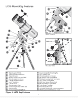
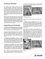
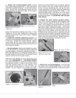
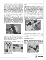
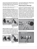
5. Attach the counterweight shaft: Locate the counterweight shaft (Fig. 1, #9) and thread down the Locking Nut (Fig. 1, #13) until it stops. Next, thread the counterweight shaft into the threaded hole on the front side of the mount, When the pointer points at your latitude, tighten both screws until they make contact with the mount. At your observing site, set up the telescope assembly so that the tripod leg below the counterweight shaft, labeled "N", (FIG. 1, #7) approximately faces True North (or True South in the Southern Hemisphere). For more informations see page 14 LOCATING THE CELESTIAL POLE. Figure 10: Set the latitude Figure 9: Attach the counter- weight shaft below the declination setting circle (Fig. 1, #14). Tighten to a firm feel. Adjust the Locking Nut upward toward the mount until it stops. Tighten to a firm feel. 6. Install the latitude adjusting screws: Locate the two threaded latitude knobs (Fig. 1, #6) in the box. Thread the longer latitude adjustment knob into the rear of the mount and the shorter latitude adjustment knob into the front of the mount as shown. 8. Attach the slow motion control cables: The LX70 comes equipped with flexible slow motion control cables for both the RA & Dec axes. Each cable is securely fastened on each axis by a small Phillips head screw. Locate the RA worm shaft mounting location and notice that it has a flat portion on one side(see Fig 13). Slide one of the cables onto the shaft so the Phillips head locking screw is aligned with the flat portion on the shaft. Using the included Phillips screw driver, secure the slow motion control cable onto the shaft until firm. Repeat this process for the declination cable(see Fig 14). 7. Set the latitude: Setting the latitude is easier if it is set before you attach the optical tube and counterweights. Locate the latitude dial (Fig. 1, #8); note that there is a triangular pointer above the dial located on the mount. The pointer is not fixed; it moves as the mount moves. Figure 13: Attach the RA slow motion control cable Figure 14: Attach the DEC slow motion control cable Determine the latitude of your observing location. See APPENDIX C: LATITUDE CHART for a list of latitudes, or check the internet. Move the latitude screws in order to move the mount until the pointer points to your latitude. The two latitude screws work in a "push - pull" operation-as you tighten one, loosen the other. 9. Attach the counterweight(s): Look through the hole in the counterweight (Fig. 1, #11) and note the pin blocking the hole. Loosen the coun- Pointer Figure 11: Latitude pointer Figure 12: North tripod leg Figure 15: Remove the safety nut Figure 16: Install the counterweight 8
-
 1
1 -
2
-
 3
3 -
 4
4 -
 5
5 -
 6
6 -
 7
7 -
 8
8 -
 9
9 -
 10
10 -
 11
11 -
 12
12 -
 13
13 -
14
-
15
-
16
-
17
-
18
-
19
-
20
-
21
-
22
-
23
-
24
-
25
-
26
-
27
-
28
 |
 |
