Meade LX70 Reflector 8 inch User Manual - Page 9
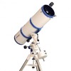
Newtonian Reflector Models only Fig 3
 |
View all Meade LX70 Reflector 8 inch manuals
Add to My Manuals
Save this manual to your list of manuals |
Page 9 highlights
terweight lock knob so the pin is not obstruct- will need to balance the telescope before use. ing the hole. Unscrew the safety cap (Fig. 1, See the section BALANCING THE TELE#10) from the shaft. Holding the counterweight SCOPE. firmly in one hand, slip the counterweight to approximately the midpoint of the counterweight 11. Assemble the viewfinder: Locate the viewshaft. Tighten the counterweight lock knob(Fig. finder bracket. Carefully remove the rubber O1, #12) to a firm feel. Replace the safety cap. ring from the bracket and position the O-ring Note: If the counterweight ever slips, the safety into the groove located approximately half-way cap prevents the counterweight from sliding en- down the viewfinder tube(see Fig 18 & 19). Untirely off the shaft. Always leave the safety cap screw the black alignment screws on the brackin place when the counterweight is on the shaft. et and slide the viewfinder optical tube until the O-ring seats into the bracket. One alignment 10. Attach the optical tube: Before attaching screw on the bracket is spring loaded to allow the optical tube, lock both the RA and DEC axes easier alignment of the viewfinder. Pull out on (Fig. 1, #17 & 18) so the mount does not move the spring loaded alignment screw to retract it, during installation. Verify the cradle ring lock allowing the viewfinder tube to fit properly into knobs (Fig. 2 or 3, #27) are tight and securely the bracket. When the O-ring is properly seated fastened to the OTA. The cradle rings should be in the bracket, tighten the two alignment screws roughly centered on the OTA during installation. to secure the viewfinder in place. While firmly holding the optical tube with both hands, slide the cradle assembly onto the cradle mounting slot at the top of the mount(see Fig 17). Figure 20: Attaching the viewfinder bracket 12. Attach viewfinder bracket: Slide the view- finder bracket into its receiver on the OTA (Fig. Figure 17: Tightening the dovetail lock knobs 2 - 4, #36). To secure the viewfinder to the tele- scope, tighten the viewfinder bracket lock knob Tighten both OTA dovetail lock knobs (Fig. 1, to a firm feel. #24) onto the dovetail rail (Fig. 2 - 4, #26) to a firm feel. The cradle rings and OTA will now be 13. Insert the eyepiece: securely fastened to the mount. Newtonian Reflector Models only (Fig 3): After attaching all accessories to the OTA, you Lift to remove the dust cap from the eyepiece holder on the focuser assembly (Fig 3, #30). Set the dust cap aside in a safe place and replace it Figure 19: Installing the viewfinder o-ring Figure 18: Viewfinder parts 9 Figure 21: Insert the 26mm eyepiece
-
 1
1 -
2
-
3
-
 4
4 -
 5
5 -
 6
6 -
 7
7 -
 8
8 -
 9
9 -
 10
10 -
 11
11 -
 12
12 -
 13
13 -
 14
14 -
15
-
16
-
17
-
18
-
19
-
20
-
21
-
22
-
23
-
24
-
25
-
26
-
27
-
28
 |
 |
