Meade LX90-ACF 8 inch User Manual - Page 4
Quick-start Guide
 |
View all Meade LX90-ACF 8 inch manuals
Add to My Manuals
Save this manual to your list of manuals |
Page 4 highlights
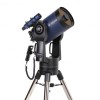
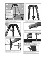
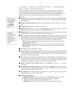
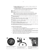
4 QUICK-START GUIDE It is recommended that you attach the supplied tripod to the LX90 for observing. Perform the telescope and AutoStar setup indoors in the light so that you become familiar with the parts and operation before moving the telescope outside into the dark for observing. Getting the telescope ready for first observations requires only a few minutes. When first opening the packing box, note carefully the following parts: • LX90 Telescope with fork mount system • AutoStar handbox and interface coil cord • Eyepiece holder and 1.25" diagonal prism • 8 x 50 Viewfinder • Super Plössl 26mm eyepiece • Variable height tripod and mounting base • Set of hex wrenches • Bubble Level / Compass Eyepiece Insert ᕡ How to Attach the Tripod to the Telescope Assembly The Field Tripod is supplied as a completely assembled unit, except for the spreader bar (Pg. 5, Fig. A, 4). For visual observations and short exposure astro-imaging, the drive base of the telescope's fork mount is attached directly to the field tripod. The telescope in this way is mounted in an "Altazimuth" ("Altitude-Azimuth," or "verticalhorizontal") format. Note: The field tripod also can be sued in conjunction with the optional equatorial wedge (see EQUATORIAL WEDGE, page 51) for long exposure astrophotography. The equatorial wedge permits alignment of the telesope's Polar Axis with the Celestial Pole (or North Star). After removing the field tripod from its shipping carton, stand the tripod vertically, with the tripod feet down and with the tripod still fully collapsed (Pg. 5, Fig. B). Grasp two of the tripod legs and, with the full weight of the tripod on the third leg, gently pull the legs apart to a fully open position (Pg. 5, Fig. C). CAUTION: "Firm feel" tightening is sufficient; over-tightening may strip the threads or damage the tripod and results in no additional strength. The spreader bar (Pg. 5, Fig. A, 4) has been removed for shipment. Unscrew the attachment nuts and spring from the spreader bar's threaded rod (Pg. 5, Fig. A, 2). Leave the washer on the bar. See Fig. D on page 5. Slide the spring into the hole on top of the tripod head (Pg. 5, Fig. A, 1). Slide the spreader bar onto the threaded rod on top of the washer that is already on the threaded rod. Position the spreader bar with the flat side facing upward (Pg. 5, Fig. E). Slide the threaded rod back through the tripod head from underneath and through the spring. Rethread the first attachment nut over the threaded rod as far down as it will go. Then thread the second nut until it is on top of the first nut. Push the rod up higher from underneath to make it easier to attach the nuts. See Fig. F and G on page 5. Move the spreader bar so that the 3 arms of the spreader bar are lined up with the 3 tripod legs. Place the entire telescope onto the top of the tripod head, and thread the rod into the central threaded hole in the bottom of the drive base of the telescope. Tighten the T-handle tension knob (Pg. 5, Fig. A, 3); firm tightening of the tension knob is sufficient to result in rigid positioning of the tripod legs. It is not necessary to use extreme force in tightening this knob. To vary the tripod height, loosen the 3 leg lock-lever and slide the 3 inner tripod leg sections out to the desired height making sure the tripod head is approximately level. Retighten the 3 lock-lever to a firm feel (Pg. 5, Fig. H). To collapse the tripod (after removing the telescope), rotate the spreader bar 60° from its assembled position, so that one spreader bar arm is located between each adjacent pair of tripod legs. At the base of the tripod is a 3-vane extension strut system, with a circular hub at its center (Pg. 5, Fig. A, 7). Grasp the tripod head (Pg. 5, Fig. A, 1) with one hand and, with the other hand, pull directly "up" on the central hub of the extension strut system. This operation will cause the tripod legs to move inward to a collapsed position. See Fig. B on page 5. CAUTION: If the tripod does not seem to extend or collapse easily, do not force the tripod legs in or out. By following the instructions above, the tripod will function properly, but if you are unclear on the proper procedure, forcing the tripod into an incorrect position may damage the extension strut system.
-
 1
1 -
 2
2 -
 3
3 -
 4
4 -
 5
5 -
 6
6 -
 7
7 -
 8
8 -
 9
9 -
 10
10 -
11
-
12
-
13
-
14
-
15
-
16
-
17
-
18
-
19
-
20
-
21
-
22
-
23
-
24
-
25
-
26
-
27
-
28
-
29
-
30
-
31
-
32
-
33
-
34
-
35
-
36
-
37
-
38
-
39
-
40
-
41
-
42
-
43
-
44
-
45
-
46
-
47
-
48
-
49
-
50
-
51
-
52
-
53
-
54
-
55
-
56
-
57
-
58
-
59
-
60
 |
 |
