Meade NG 114mm User Manual - Page 10
Red Dot Viewfinder, Red Dot Viewfinder Alignment Screws
 |
View all Meade NG 114mm manuals
Add to My Manuals
Save this manual to your list of manuals |
Page 10 highlights
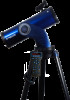
REFLECTING TELESCOPE FEATURES Take the time to become acquainted with your reflecting telescope and all of these controls before attempting observations through the telescope. Refer to Figure 2a. 1. Focus Knob: Moves the telescope's focus drawtube in a finely-controlled motion to achieve precise image focus. Rotate the focus knob clockwise to focus on distant objects, and counterclockwise to focus on nearby objects. 2. Eyepiece Holder Thumbscrew: Tightens the eyepiece in place. Tighten to a firm feel only. 3. Eyepiece Holder: Holds the eyepiece in place. 4. Primary Mirror Collimation Adjustment Screws: Adjustment and locking screws for tipping and tilting the primary mirror. See page 40 for more information. 5. Eyepiece: Place the supplied eyepiece into the Eyepiece Holder and tighten in place with the thumbscrew. 6. Focus Lock Knob: Designed to prevent the focuser drawtube from moving when a heavy accessory, such as a camera, is attached to the focuser assembly. For normal observing with an eyepiece it is not necessary to use the lock knob. 7. Red Dot Viewfinder: Provides an easier way to initially sight objects than the main telescope eyepiece which has a narrower field of view. Rotate the knob on the front of the red dot viewfinder to turn on the device and to change the intensity of the red dot. 8. Red Dot Viewfinder Alignment Screws: Adjust these screws to align the viewfinder. See page 15 for more information. 9. Dovetail Receiver: Attaches the optical tube to the mount and secures it in place with a single locking screw. 10. Altitude Setting Circle and Lock: The setting circle displays Altitude (vertical) coordinates (E, Fig. 2b). The Altitude Lock controls the manual vertical movement of the telescope. Turning the Altitude lock counterclockwise unlocks the telescope enabling it to be freely tilted by hand on the vertical axis. Turning the Altitude lock clockwise (to a firm feel only) prevents the telescope from being moved manually and engages the vertical motor drive clutch for AudioStar operation (F, Fig. 2b). 11. Optical Tube Assembly (OTA): The main optical component that gathers the light from distant objects and brings this light to a focus for observation with the eyepiece. 12. Secondary Mirror Collimation Adjustment Screws: Adjustment screws for tipping and tilting the secondary mirror. See page 40 for more information. 13. Dust Cap: Pull to remove the dust cap from the front lens of the telescope. Note: The dust cap should be replaced and the power turned off to the telescope after each observing session. Verify that any dew that might have collected during the observing session has evaporated before replacing the dust cap. 14. Mount Body: Holds the optical tube assembly. Attaches to the tripod base (17, Fig. 2). 15. Computer Control Panel (Fig. 2c) A. Hand box (HBX) Port: Plug the AudioStar hand box B. LED: The red power indicator light illuminates when power is supplied to the connected hand box and to the telescope's motor drive. Looking at or near the Sun will cause irreversable damage to your eye. Do not point this telescope at or near the Sun. Do not look through the telescope as it is moving. 10
-
 1
1 -
2
-
3
-
4
-
 5
5 -
 6
6 -
 7
7 -
 8
8 -
 9
9 -
 10
10 -
 11
11 -
 12
12 -
 13
13 -
 14
14 -
 15
15 -
16
-
17
-
18
-
19
-
20
-
21
-
22
-
23
-
24
-
25
-
26
-
27
-
28
-
29
-
30
-
31
-
32
-
33
-
34
-
35
-
36
-
37
-
38
-
39
-
40
-
41
-
42
-
43
-
44
-
45
-
46
-
47
-
48
-
49
-
50
-
51
-
52
 |
 |
