Metabo W 14-150 Ergo Operating Instructions - Page 17
Attaching the grinding, wheel
 |
View all Metabo W 14-150 Ergo manuals
Add to My Manuals
Save this manual to your list of manuals |
Page 17 highlights
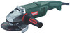
ENGLISH ENG parting work is performed (see chapter 11 Accessories). See illustration E on page 3. - Push and hold the lever (12). Place the safety guard (9) in the position indicated. - Release the lever and turn the safety guard until the lever engages. - Push the lever and turn the safety guard until the closed section is facing the operator. - Make sure that the guard is seated securely: the lever must engage and you should not be able to turn the safety guard. 6.3 Rotatable main handle Only work with the main handle (7) engaged. See illustration B on page 3. - Push in the button (6). - The main handle (7) can now be turned 90° to both sides and can be engaged. - Make sure that it is securely positioned: the main handle (7) must be engaged and it should not be possible to move it. 6.4 Power supply The mains sockets must be protected using timedelay fuses or circuit breakers. supporting flange. The metal flange on the parting grinder disc must lay flat on the support flange. 7.3 Securing/Releasing the clamping nut Securing the clamping nut (10): The 2 sides of the clamping nut are different. Screw the clamping nut onto the spindle as follows: See illustration D on page 3. - A) For thin grinding wheels: The edge of the clamping nut (10) faces upwards so that the thin grinding wheel can be attached securely. B) For thick grinding wheels: The edge of the clamping nut (10) faces downwards so that the clamping nut can be attached securely to the spindle. - Lock the spindle. Turn the clamping nut (10) clockwise using the 2-hole spanner (11) to secure. Releasing the clamping nut: - Lock the spindle (see chapter 7.1). Turn the clamping nut (10) anticlockwise using the 2-hole spanner (11) to unscrew. 7 Attaching the grinding wheel 8 Use Disconnect the mains plug before changing any accessories. The machine must be switched off and the spindle at a standstill. For reasons of safety, attach the parting guard before performing parting work (see chapter 11 Accessories). 7.1 Locking the spindle Press in the spindle locking button (3) only when the spindle is stationary! - Press in the spindle locking button (3) and turn the spindle (2) by hand until you feel the spindle locking button engage. 7.2 Placing the grinding wheel in position See illustration C on page 3. - Fit the support flange (1) on the spindle. The flange should not turn on the spindle when properly attached. - Position the grinding wheel on the support flange (1) as shown in illustration C. The grinding wheel must lay flat on the 8.1 Switching On and Off Always guide the machine with both hands. Switch on first, then guide the accessory towards the workpiece. The machine must not be allowed to draw in additional dust and shavings. When switching the machine on and off, keep it away from dust deposits. After switching off the machine, only place it down when the motor has come to a standstill. Avoid inadvertent starts: always switch the tool off when the plug is removed from the mains socket or if there has been a power cut. In continuous operation, the machine continues running if it is forced out of your hands. Therefore, always hold the machine with both hands at the intended handles, take a secure stance and concentrate on the work. See illustration A on page 3. 17
-
 1
1 -
2
-
3
-
4
-
5
-
6
-
7
-
8
-
9
-
10
-
11
-
 12
12 -
 13
13 -
 14
14 -
 15
15 -
 16
16 -
 17
17 -
 18
18 -
 19
19 -
 20
20 -
 21
21 -
 22
22 -
23
-
24
-
25
-
26
-
27
-
28
-
29
-
30
-
31
-
32
-
33
-
34
-
35
-
36
-
37
-
38
-
39
-
40
-
41
-
42
-
43
-
44
-
45
-
46
-
47
-
48
-
49
-
50
-
51
-
52
-
53
-
54
-
55
-
56
-
57
-
58
-
59
-
60
-
61
-
62
-
63
-
64
-
65
-
66
-
67
-
68
-
69
-
70
-
71
-
72
-
73
-
74
-
75
-
76
-
77
-
78
-
79
-
80
-
81
-
82
-
83
-
84
-
85
-
86
-
87
-
88
-
89
-
90
-
91
-
92
-
93
-
94
-
95
-
96
-
97
-
98
-
99
-
100
-
101
-
102
-
103
-
104
-
105
-
106
-
107
-
108
-
109
-
110
-
111
-
112
-
113
-
114
-
115
-
116
-
117
-
118
-
119
-
120
-
121
-
122
-
123
-
124
 |
 |
