Milwaukee Tool M18 FUEL 1/2" HTIW & 3/8" MTIW Automotive Combo Kit Service Par - Page 2
squarely in the handle recesses.
 |
View all Milwaukee Tool M18 FUEL 1/2" HTIW & 3/8" MTIW Automotive Combo Kit manuals
Add to My Manuals
Save this manual to your list of manuals |
Page 2 highlights
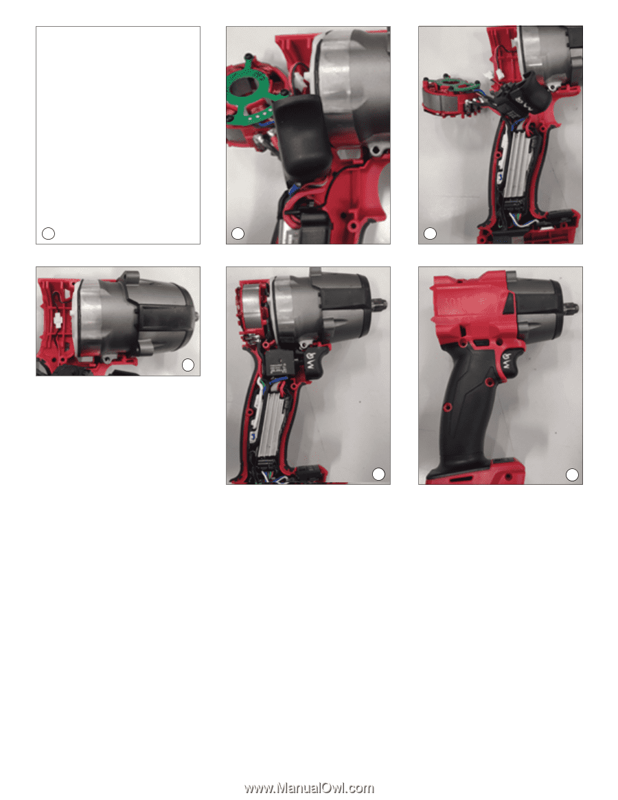
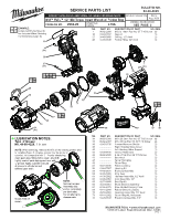
1 2 3 4 1. Install the HV (ground) terminal being sure that the clip is inserted in housing cavity. Place ground wire in wire channel and route as shown. 2. Place gearcase assembly in housing halve and secure with two gearcase screws. 3. Install the PCBA in housing halve. Place mode selector assembly as shown. 5 6 4. Join the connector of shadowless LED assembly with connector on electronics assembly. Route wires in traps as shown. 5. Place into housing halve the remaining components of the electronics assembly (stator, on-off switch and forward/reverse shuttle). 6. Install the housing cover onto the housing support. Secure housing halves with screws. Secure gearcase assembly to housing assembly with remaining two screws. Not shown: Install rotor assembly onto rear of housing assembly and secure with four screws. As an aid to reassembly, take notice of wire routing and position in wire guides and traps while dismantling tool. Be sure that all components of electronics kit are seated firmly and squarely in the handle recesses. Avoid pinched wires, be sure that all wires and sleeves are pressed completely down in wire guides and traps. Prior to securing the handle cover onto the handle support, be sure that there are no interferences. Before installing the battery, check for proper functionality of shuttle and triggers. Install battery and depress switch trigger to assure tool is operating properly.
-
 1
1 -
 2
2
 |
 |