Milwaukee Tool Utility Remote Control Search Light Operators Manual - Page 3
Assembly, Functional Description, Operation, Maintenance
 |
View all Milwaukee Tool Utility Remote Control Search Light manuals
Add to My Manuals
Save this manual to your list of manuals |
Page 3 highlights
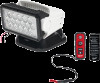
FUNCTIONAL DESCRIPTION 1 2 3 4 5 6 1. Light head 2. ONE-KEY™ indicator 3. Mode button 4. Home button 5. Power button 6. Portable base 7. Battery compartment 7 latches 8. Battery door 8 9. 12V DC Permanent base 2 9 10 11 12 13 ASSEMBLY WARNING Recharge only with the specified for the battery. charger For spe- cific charging instructions, read the operator's manual supplied with your charger and battery. Removing/Inserting the Battery To remove the battery, lift the battery door latches and open the battery door. Push in the battery release buttons and pull the battery pack away from the tool. Close the battery door and relatch the door latches securely. WARNING Always remove battery pack before changing or removing accessories. To insert the battery, lift the battery door latches and open the battery door. Slide the pack into the body of the tool. Make sure it latches securely into place. Close the battery door and relatch the door latches securely. WARNING Only use accessories recommended for this specifically tool. Others may be hazardous. Installing the Base WARNING The base should be installed according to the vehicle manufac- turer's specifications by a qualified technician. Drilling holes in certain structural areas, or wiring incorrectly, could compromise the safety of the vehicle. To mount the permanent base: 1. Place the base on the desired location. Make sure it is on a clean, dry surface. 2. Mount the base to the location using four 1/4" screws. 3. Connect to the vehicle's wiring per the manufac- turer's wiring schematic. WARNING Do not use magnet for overhead mounting. horizontal To mount the portable base: Select the best location on your vehicle for the magnetic mount. Make sure the metal area under the magnetic base is flat and clean to ensure a strong bond. WARNING! Excessive force will break the magnet free. The light should be removed from a vehicle's exterior while traveling and in strong wind conditions. 10. Mounting accessories 11. Power leads 12. Remote light power button 13. Remote on/off switch 14. Remote joystick 15. Remote mode button 16. Instensity button 17. Lanyard (not shown) 18. Remote dash mount 14 15 16 17 18 Attaching/Removing the Light WARNING Inspect the during the mounting screw daily required daily vehicle inspection. If the screw is not tightly secured the light could detach from the base. A light that detaches from the base while the vehicle is in motion is a road hazard and could cause serious injury or death to others. The light head can either be attached to the 12V DC permanent base or portable base. To assist in re- configuring the light, utilize the included screw kit and hex key. To attach, secure the light head into the body of the base with the mounting screw. Make sure the screw is tightened securely into place. To remove, unscrew the mounting screw from the body of the base and pull the light head away from the base. NOTE: The 12V DC permanent base and portable base features a screw hole (M6 x 1 thread) that can be used to further secure the light head to the base. Attaching the Remote Dash Mount WARNING To or reduce death, the risk of serious injury install the remote dash mount away from vehicle functions and safety features, such as air bags. Air bag deployment could cause the remote to become a projectile. Make sure the surface is clean and dry before at- taching. To attach, peel the protective layer from the back of the remote dash mount. Place the mount on the desired surface. Let the mount cure for 24 hours before removing the remote from mount. ONE-KEY™ To learn more about the ONE-KEY™ functionality for this tool, go to milwaukeetool.com/One-Key. To download the ONE-KEY™ app, visit the App Store or Google Play from your smart device. Solid Blue ONE-KEY™ Indicator Wireless mode is active and ready to be configured via the ONE-KEY™ app. Blinking Blue Tool is actively communicating with the ONE-KEY™ app. Blinking Red Tool is in security lockout and can be unlocked by the owner via the ONE-KEY™ app. OPERATION WARNING To reduce the risk of injury, do look directly into the light when not the light is ON. To turn ON the light, press the Power button . To turn OFF the light, press the Power button again . To turn ON the remote, turn the Remote on/off switch ON. Press the MODE button to cycle through spot, flood low, and flood high light settings. To rotate the light, use the remote joystick . To adjust the speed of rotation, click down on the remote joystick . To return the light to the home position, press and hold the remote home button for two seconds. MAINTENANCE WARNING To reduce the risk of injury, always unplug the charger and remove the battery pack from the charger or tool before performing any maintenance. Never disassemble the tool, battery pack or charger. Contact a MILWAUKEE service facility for ALL repairs. Maintaining Tool Keep your tool, battery pack and charger in good repair by adopting a regular maintenance program. Inspect your tool for issues such as undue noise, misalignment or binding of moving parts, breakage of parts, or any other condition that may affect the tool operation. Return the tool, battery pack, and charger to a MILWAUKEE service facility for repair. After six months to one year, depending on use, return the tool, battery pack and charger to a MILWAUKEE service facility for inspection. If the tool does not start or operate at full power with a fully charged battery pack, clean the contacts on the battery pack. If the tool still does not work properly, return the tool, charger and battery pack, to a MILWAUKEE service facility for repairs. 4 5
-
 1
1 -
 2
2 -
 3
3 -
 4
4 -
 5
5 -
 6
6 -
 7
7 -
 8
8 -
 9
9 -
10
-
11
 |
 |
