Motorola 2241N-VGX Quick Start Guide - Page 2
Set up your Gateway, Configure Your PCs for DHCP - dsl
 |
View all Motorola 2241N-VGX manuals
Add to My Manuals
Save this manual to your list of manuals |
Page 2 highlights
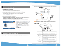
2 Set up your Gateway 1.Decide the location for the Gateway. Put the Gateway in a location where air can circulate freely around it. 2.Connect the power supply to the power jack on the back panel of the Gateway. Then, plug the power supply into an electrical outlet. Turn on the Power switch. The Power light should light solid green. 3.Insert the Netopia CD into your CDROM drive. The Netopia Installation Guide Wizard automates several tasks to get you up and running easily. You can run the Wizard on every Windows-based PC that will connect to your network. The Installation Guide Wizard will run automatically and step through your connection installation(s). The Installation Guide Wizard lets you choose which type of Netopia device you are installing, and where you are installing it. Choose either Install via Ethernet or Install USB Connection. The Netopia Installation Guide Wizard will install USB drivers if you choose the USB option. Click the Next button. Follow the on-screen instructions to make all of your connections. 3 Configure Your PCs for DHCP Be sure to configure each computer connected to your Netopia Gateway to accept a Dynamically-assigned IP address, commonly referred to as DHCP. 2 When all of your connections are made, your connections should look like this: Rear View DSL Port USB Port Ethernet Port Power Switch Telephone/DSL jack RESET OFF ON DSL USB ETHERNET POWER 2 (optional) Power outlet 2 Connect via Ethernet or USB. DC Power Note: You will need an extra hub or switch if more Ethernet ports are needed. Front View LED Power Ethernet USB DSL Internet Power Ethernet USB Internet DSL Behavior Green when power is on. Red if device malfunctions. Solid green when connected. Flashes green when there is activity on the LAN. Solid green when connected. Flashes green when there is activity on the LAN. Solid green when Internet connection is established. Solid green when Gateway is connected. Flashes green when transmitting or receiving data on the WAN port. 3
-
 1
1 -
 2
2
 |
 |
