NEC C651Q External Controls - Page 122
Bit0: ALL INPUT is OFF 0.
 |
View all NEC C651Q manuals
Add to My Manuals
Save this manual to your list of manuals |
Page 122 highlights
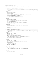
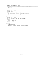
Bit6: OSD Bit7: MULTI DISP Bit8: PROTECT Bit9: EXT-CTRL Bit10: ADVANCED Bit11: ADVANCED2 Bit12: HTTP Bit13: Reserve Bit14: Reserve Bit15: Reserve Ex.) Setting the following value for T4 Bit0: ALL INPUT is OFF (0). Bit1: PICTURE is OFF (0). Bit2: ADJUST is ON (1). Bit3: AUDIO is ON (1). Step 1: Put above bit in following order. Bit3-Bit2-Bit1-Bit0 Value: 1100 Step 2: Write the value of Step 1 by a hexadecimal number. Value: 0Ch Step 3: Encode the value of Step 2 to ASCII characters. Value: '0' and 'C' (30h and 43h) ETX (03h): End of Message Check code BCC: Block Check Code Refer to the section 4.3 "Check code" for a BCC calculation. Delimiter CR (0Dh): End of packet (122/145)
-
 1
1 -
2
-
3
-
4
-
5
-
6
-
7
-
8
-
9
-
10
-
11
-
12
-
13
-
14
-
15
-
16
-
17
-
18
-
19
-
20
-
21
-
22
-
23
-
24
-
25
-
26
-
27
-
28
-
29
-
30
-
31
-
32
-
33
-
34
-
35
-
36
-
37
-
38
-
39
-
40
-
41
-
42
-
43
-
44
-
45
-
46
-
47
-
48
-
49
-
50
-
51
-
52
-
53
-
54
-
55
-
56
-
57
-
58
-
59
-
60
-
61
-
62
-
63
-
64
-
65
-
66
-
67
-
68
-
69
-
70
-
71
-
72
-
73
-
74
-
75
-
76
-
77
-
78
-
79
-
80
-
81
-
82
-
83
-
84
-
85
-
86
-
87
-
88
-
89
-
90
-
91
-
92
-
93
-
94
-
95
-
96
-
97
-
98
-
99
-
100
-
101
-
102
-
103
-
104
-
105
-
106
-
107
-
108
-
109
-
110
-
111
-
112
-
113
-
114
-
115
-
116
-
 117
117 -
 118
118 -
 119
119 -
 120
120 -
 121
121 -
 122
122 -
 123
123 -
 124
124 -
 125
125 -
 126
126 -
 127
127 -
128
-
129
-
130
-
131
-
132
-
133
-
134
-
135
-
136
-
137
-
138
-
139
-
140
-
141
-
142
-
143
-
144
-
145
 |
 |

(122/145)
Bit6: OSD
Bit7: MULTI DISP
Bit8: PROTECT
Bit9: EXT-CTRL
Bit10: ADVANCED
Bit11: ADVANCED2
Bit12: HTTP
Bit13: Reserve
Bit14: Reserve
Bit15: Reserve
Ex.) Setting the following value for T4
Bit0: ALL INPUT is OFF (0).
Bit1: PICTURE is OFF (0).
Bit2: ADJUST is ON (1).
Bit3: AUDIO is ON (1).
Step 1: Put above bit in following order.
Bit3-Bit2-Bit1-Bit0
Value: 1100
Step 2: Write the value of Step 1 by a hexadecimal number.
Value: 0Ch
Step 3: Encode the value of Step 2 to ASCII characters.
Value: '0' and 'C' (30h and 43h)
ETX (03h): End of Message
Check code
BCC: Block Check Code
Refer to the section 4.3
“
Check code
”
for a BCC calculation.
Delimiter
CR (0Dh): End of packet