NEC NP-M300W M260W : user's manual - Page 130
(4) Pin Assignments of D-Sub COMPUTER Input Connector, Appendix, Mini D-Sub 15 Pin Connector
 |
UPC - 805736035636
View all NEC NP-M300W manuals
Add to My Manuals
Save this manual to your list of manuals |
Page 130 highlights
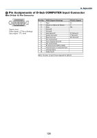
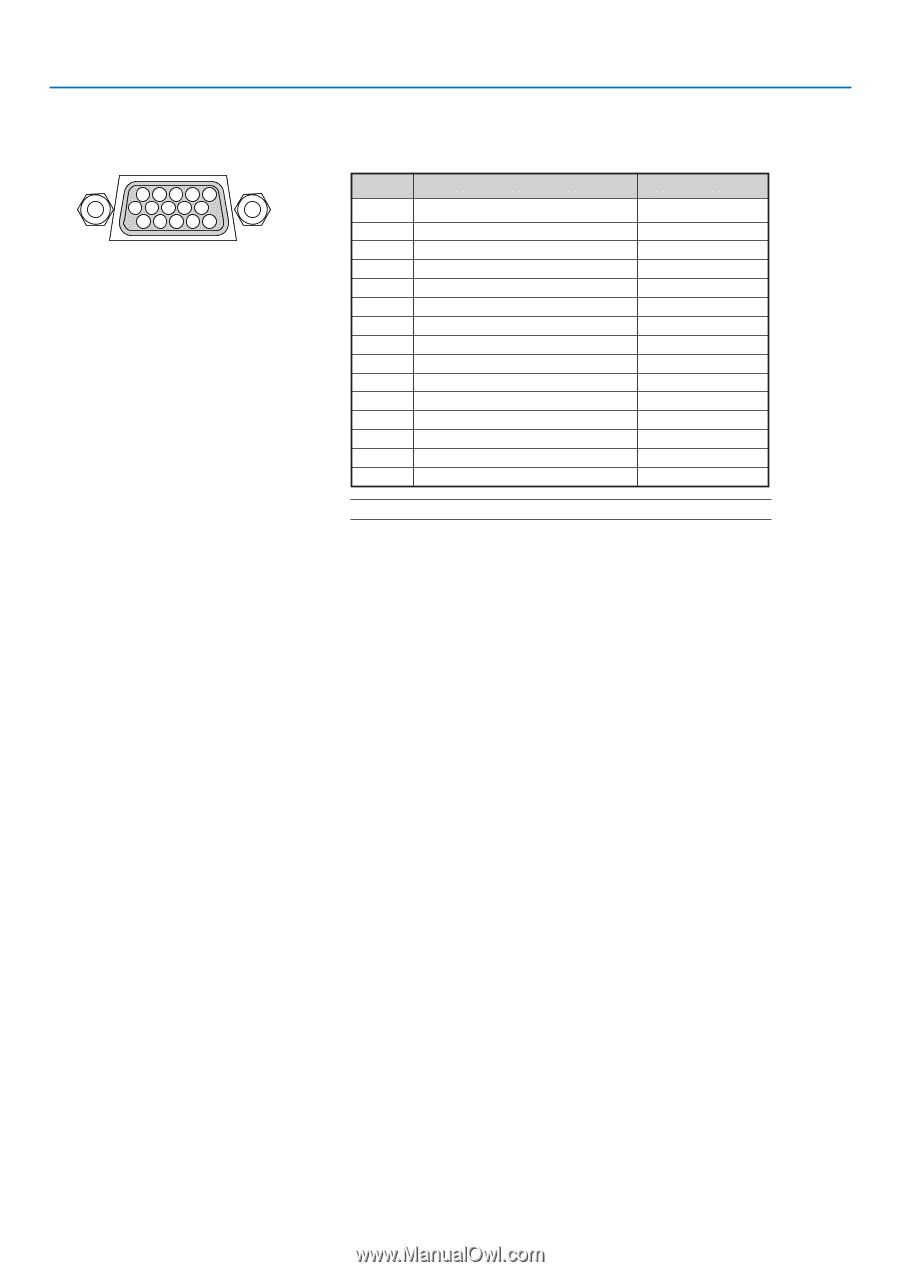
8. Appendix 4 Pin Assignments of D-Sub COMPUTER Input Connector Mini D-Sub 15 Pin Connector 11 12 13 14 15 6 7 8 9 10 1 23 45 Signal Level Video signal : 0.7Vp-p (Analog) Sync signal : TTL level Pin No. 1 2 3 4 5 6 7 8 9 10 11 12 13 14 15 RGB Signal (Analog) Red Green or Sync on Green Blue Ground Ground Red Ground Green Ground Blue Ground No Connection Sync Signal Ground No Connection Bi-directional DATA (SDA) Horizontal Sync or Composite Sync Vertical Sync Data Clock YCbCr Signal Cr Y Cb Cr Ground Y Ground Cb Ground NOTE: Pin Nos. 12 and 15 are required for DDC/CI. 120
-
 1
1 -
2
-
3
-
4
-
5
-
6
-
7
-
8
-
9
-
10
-
11
-
12
-
13
-
14
-
15
-
16
-
17
-
18
-
19
-
20
-
21
-
22
-
23
-
24
-
25
-
26
-
27
-
28
-
29
-
30
-
31
-
32
-
33
-
34
-
35
-
36
-
37
-
38
-
39
-
40
-
41
-
42
-
43
-
44
-
45
-
46
-
47
-
48
-
49
-
50
-
51
-
52
-
53
-
54
-
55
-
56
-
57
-
58
-
59
-
60
-
61
-
62
-
63
-
64
-
65
-
66
-
67
-
68
-
69
-
70
-
71
-
72
-
73
-
74
-
75
-
76
-
77
-
78
-
79
-
80
-
81
-
82
-
83
-
84
-
85
-
86
-
87
-
88
-
89
-
90
-
91
-
92
-
93
-
94
-
95
-
96
-
97
-
98
-
99
-
100
-
101
-
102
-
103
-
104
-
105
-
106
-
107
-
108
-
109
-
110
-
111
-
112
-
113
-
114
-
115
-
116
-
117
-
118
-
119
-
120
-
121
-
122
-
123
-
124
-
 125
125 -
 126
126 -
 127
127 -
 128
128 -
 129
129 -
 130
130 -
 131
131 -
 132
132 -
 133
133 -
 134
134 -
 135
135 -
136
 |
 |
120
8. Appendix
Mini D-Sub 15 Pin Connector
Pin Assignments of D-Sub COMPUTER Input Connector
Signal Level
Video signal : 0.7Vp-p (Analog)
Sync signal : TTL level
5
1
4
2
3
10
11
12
13 14
15
6
9
7
8
NOTE: Pin Nos. 12 and 15 are required for DDC/CI.
Pin No.
RGB Signal (Analog)
YCbCr Signal
1
Red
Cr
2
Green or Sync on Green
Y
3
Blue
Cb
4
Ground
5
Ground
6
Red Ground
Cr Ground
7
Green Ground
Y Ground
8
Blue Ground
Cb Ground
9
No Connection
10
Sync Signal Ground
11
No Connection
12
Bi-directional DATA (SDA)
13
Horizontal Sync or Composite Sync
14
Vertical Sync
15
Data Clock