Nady UB-33B Manual - Page 5
Ub-33b Bass Wireless Transmitter, U-33b Receiver
 |
View all Nady UB-33B manuals
Add to My Manuals
Save this manual to your list of manuals |
Page 5 highlights
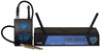
UB-33B BASS WIRELESS TRANSMITTER 1. Open the hinged BATTERY DOOR (16) and insert 2 fresh AAA ALKALINE BATTERIES into the BATTERY COMPARTMENT (17), observing the correct polarity. Fresh alkaline batteries can last up to 5 hours in use, but in order to ensure optimum performance, it is recommended that the batteries be replaced after 3-4 hours of use. 2. The UB-33B is provided with a 3.5 mm LOCKING JACK (18) for connecting the audio input selected. Connect either the INSTRUMENT CORD (24), to secure the connection, turn the slip ring on the plug clock wise to thread it on the jack. To unplug, reverse the process. Slip the transmitter into a pocket or CLIP (23) it onto your clothes or instrument strap. 3. Turn on the UB-33B by sliding the audio AUDIO SWITCH (19) to the OFF position first then slide the POWER SWITCH (21) to the ON position. The Bi-Color LED indicator (20) will stay on (GREEN), indicating usable battery strength and that the transmitter is on. In the case of dead or low batteries, the LED will either not go on at all or will stay on (ORANGE) continuously, indicating that the batteries should be replaced with fresh ones. To preserve battery life, turn the transmitter off when not in use. The A or B Diversity LED indicators (13) on the U-33 receiver should now be lit, indicating a received signal from the transmitter. 4. Instrument Use Secure the connection from the GT CABLE (24) by turning the slip ring on the plug into the transmitter clockwise to thread it on the jack. To unplug, reverse the process. Plug the 1/4" phone plug into the instrument. When ready to play, slide the AUDIO SWITCH (19) to "ON" position. Adjust the volume of the receiver as per the Audio Output Instrument Connection section of the above U-33B receiver instruction. (Note: The UB-33B is supplied with a removable antenna. It should be operated with the supplied antenna all times. For optimum operating range, always maintain lineof-sight between the transmitter and the receiver whenever possible.) 8 U-33B RECEIVER 1. Rackmounting the Receiver There are 2 options available for rackmounting the U-33B receiver: singly or side-byside with another U-33B receiver. a. Single mounting: Remove the receiver SIDE MOUNT CLIP (1) from each side of the receiver (as shown) and slide in the optional ERM-3 RACK EARS (2). b. Side-by-side double mounting: After removing the SIDE MOUNT CLIPS (1) from both U-33B receivers, join the two receivers with the EJC-3 JOINING CLIP (3) and attach the ERM-33 RACK EARS (4) as shown. (Note: Do not mount the receiver in a rack directly above an amplifier or other source of high heat - this could degrade the performance of the U-33B. Always ensure adequate airflow and heat dissipation in any rack configuration.) 2. Powering the Receiver Plug the 18V AC/DC ADAPTER (5) provided into the DC INPUT JACK (9) on the back of the receiver. Then plug the power supply into an AC outlet. (Note: Any 18V DC source with 250mA capability can also be used.) Press the POWER SWITCH (11) once to turn on the receiver. The POWER ON LED (12) will now light and the receiver is operational. 3. Antennas The U-33B receiver is supplied with FOLDING ANTENNAS (15). These should be extended fully to obtain maximum range. Optimal antenna position is 45 degrees from the receiver (at 90 degrees from each other). For maximum range, it is always best to maintain a line of sight (no obstructions) between the receiver antennas and the transmitter at all times whenever possible. 4. Mute (Squelch) Adjustment In normal operation, the SQUELCH CONTROL (6) should be set fully clockwise to the factory preset RF level (Max. Sens.). However, in areas of high RF activity, the squelch (or mute, as it is sometimes called) may need to be adjusted to compensate for the adverse conditions in a particular location. If, with the transmitter off, the receiver's A or B DIVERSITY LED INDICATORS (13) flicker or stay on, the squelch control should be turned counterclockwise until the A or B LEDs extinguish. When the squelch is properly adjusted, the A or B LEDs will only light when the system transmitter is turned on. Turning the squelch control too far counterclockwise will reduce the range, but yield a quieter squelch (mute) function. During operation, especially at ranges greater than 75 feet, one or the other of the A or B LEDs may extinguish briefly. This is normal-the unit's DigiTRU Diversity™ reception ensures that the received audio will not be interrupted. When both LEDs extinguish, the transmitter is out of range for that given location, and the user should move closer to the receiver to re-establish the radio link. 5
-
 1
1 -
 2
2 -
 3
3 -
 4
4 -
 5
5 -
 6
6
 |
 |
