Nautilus NS75X Assembly Manual - Page 11
Step 3
 |
View all Nautilus NS75X manuals
Add to My Manuals
Save this manual to your list of manuals |
Page 11 highlights
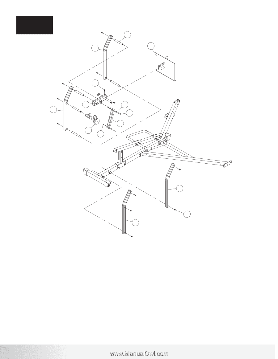
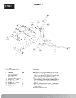
STEP 3 Assembly 29 11 9 38 8 13 39 31 1/2" x 3"L 15 14 42 Step 3 Components: # Component Qty 8 Leg Press Top Link 1 9 Foot Plate Assembly 1 10 Leg Press Front Link Left 1 11 Leg Press Front Link Right 1 12 Leg Press Rear Link Left 1 13 Leg Press Rear Link Right 1 14 Leg Press Power Arm 1 15 Leg Press Power Link 1 29 Pivot Shaft 5 31 Hex Bolt - 1/2" x 3"L 2 38 Button Head Screw - 3/8" x 3/4"L w/ Thread Lock 15 39 1/2" Flat Washer 4 42 1/2" lock Nut 2 10 38 3/8" x 3/4"L w/ THREAD LOCK 12 Procedure: A. Attach all the Pivot Shafts (29) to the Leg Press Front Link Right (11) and the Leg Press Rear Link Right (13) using the hardware shown above. B. Slide the shafts into position on the Main Base Assembly. C. Slide the Leg Press Top Link (8) and the Leg Press Power Arm (14) into position as shown above. D. Position the Leg Press Front and Rear Link Left (10, 12) over the shafts and attach with the hardware shown above. E. Connect the Leg Press Power Arm (14) to the Leg Press Top Link (8) using the Leg Press Power Link (15) and the hardware shown above. Intsall short end of Leg Press Power Link (15) up. F. Attach the Foot Plate Assembly (9) to the Leg Press Top Link (8) using the hardware shown above. G. Tighten all hardware securely. Nautilus NS75X 11
-
 1
1 -
2
-
3
-
4
-
5
-
 6
6 -
 7
7 -
 8
8 -
 9
9 -
 10
10 -
 11
11 -
 12
12 -
 13
13 -
 14
14 -
 15
15 -
 16
16 -
17
 |
 |