Netgear FS726AT FS750 Reference Manual - Page 15
Physical Description
 |
View all Netgear FS726AT manuals
Add to My Manuals
Save this manual to your list of manuals |
Page 15 highlights
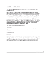
CHAPTER 2: PHYSICAL DESCRIPTION This chapter describes the hardware features of the FS726 and FS750 Switches. Topics include: • Front and back panels • 10/100 Mbps RJ-45 ports • LED Mode button and LEDs • Module bays (for copper or fiber Gigabit Ethernet modules) • Auto Uplink • Reset button Front and Back Panels Figure 2-1 shows the key components on the front and back panels of the FS726 Switch. Figure 2-2 shows the key components on the front and back panels of the FS750 Switch. The front panel of each switch contains a reset button, an LED Mode push button for alternating LED readout categories, Link LEDs, Mode LEDs, RJ-45 jacks, and two module bays for installing Gigabit Ethernet modules. Both the FS726 Switch and the FS750 Switch support Auto Uplink technology, eliminating the need for a Normal/Uplink push button. The back panel of each switch has fans for cooling, and a standard AC power receptacle for accommodating the supplied power cord. physical description 2-1
-
 1
1 -
2
-
3
-
4
-
5
-
6
-
7
-
8
-
9
-
 10
10 -
 11
11 -
 12
12 -
 13
13 -
 14
14 -
 15
15 -
 16
16 -
 17
17 -
 18
18 -
 19
19 -
 20
20 -
21
-
22
-
23
-
24
-
25
-
26
-
27
-
28
-
29
-
30
-
31
-
32
-
33
-
34
-
35
-
36
-
37
-
38
-
39
-
40
-
41
-
42
-
43
-
44
-
45
-
46
-
47
-
48
-
49
-
50
-
51
-
52
 |
 |
