Netgear GC102 GC102 Installation Guide - Page 2
Prepare The Site, Install The Converter, Connect Devices To The Converter, Verify Installation, - gigabit
 |
UPC - 606449024418
View all Netgear GC102 manuals
Add to My Manuals
Save this manual to your list of manuals |
Page 2 highlights
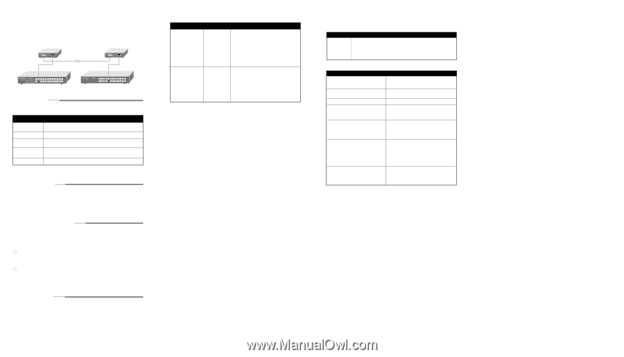
Back-to-back Two GC102 Gigabit Converters can be used to extend the reach of an all copper gigabit network, enabling a work group or department to move to a different floor or nearby building. In this example, a network based on two GS524T Gigabit Ethernet Switches remains connected via the long fiber run made possible by the GC102. GC102 Converter 100 m GS524T Switch 24PORT 10/100MbpsGigabit Fiber Switch Ethernet MODELGS524T GC102 Converter 500 m 100 m GS524T Switch 24PORT 10/100MbpsGigabit Fiber Switch Ethernet MODELGS524T PREPARE THE SITE Before you begin installing your Converter, prepare the installaiton site. Make sure your operating environment meets the operating environment requirements of the equipment. Characteristic Temperature Operating humidity Ventilation Operating conditions Power Requirement Ambient temperature between 00 and 400 C (320 and 1040F). No nearby heat sources such as direct sunlight, warm air exhausts, or heaters. Maximum relative humidity of 90%, noncondensing. Minimum 2 inches (5.08 cm) on all sides for cooling. Adequate airflow in room or wiring closet. At least 6 feet (1.83 m) to nearest source of electromagnetic noise (such as photocopy machine or mace welder) Adequate power source within 6 feet (1.83 m). Warning: Class 1 laser device. Warning: Do not stare into the laser beam. INSTALL THE CONVERTER To install your converter on a flat surface, you do not need any special tools. Be sure the converter is positioned with at least 2 inches of space on all sides for ventilation. To install the converter on a wall, measure the distance between the mounting holes on the back of the converter and mark the wall to match the location of the mounting holes on the converter. At the marks, screw into the wall the two screws in the mounting kit included in your package contents. Choose a location that is near the devices to be connected, is close to an electrical outlet, and provides at least 2 inches of space all around the converter for ventilation. CONNECT DEVICES TO THE CONVERTER Before connecting the converter, be sure to review "Applications" on page 2 to determine the appropriate configuration for your networking needs. To connect the converter : 1.Connect the devices to the RJ-45 port on the converter, using Category 5 UTP cable and an RJ-45 plug. Note: Ethernet specifications limit the cable length between your converter and your switch, server or PC to 328 feet (100 meters). 2. Connect the device to the SC port on the converter, using mulitmode fiber cable and an SC connector. Note: Ethernet specifications limit the cable length between your converter and your switch, server, or PC to 1,804 feet (550 meters). 3.Connect one end of the power adapter to the power outlet on the rear panel of the switch and the other end of the power adapter cable to the wall outlet. VERIFY INSTALLATION When power has been applied to the Converter : The green PWR (Power) LED on the front panel is on. The green LNK LED on each connected port is on. Refer to the table in the "LEDs" section for information about the LEDs and their activity. TROUBLESHOOTING INFORMATION Symptom Green Link LED is off on an active port Green Link LED intermittent the Cause Port connection is not functioning Port connection is not functioning. an active port. Solution Make sure the attached device is powered and there is a proper connection at that end. Make sure the network adapter card installed in the PC is working. Verify that the network adapter card is 1000 Mbps capable and that the 1000 Mbps LED and Link LEDs are on at the network adapter card in the PC. Make sure the proper cable is installed, and check for miswired cable pairs or loose connectors. Make sure the port termination at the Netgear GC102 Converter end and the device end are correct. Check crimp on the RJ-45 connectors. It is also important that Category 5 cable or better is used and that it is certified for 1000 Mbps operation. Make sure the length of the UTP cable from the converter to the device does not exceed 328 feet (100 meters) for copper connections or 1,804 feet (550 meters) for fiber connections. REPLACEMENT POWER ADAPTER If, for any reason, the power adapter for any of the hubs fails, please contact NETGEAR immediately to order a replacement adapter. Use the following table when ordering a specific power adapter. Order Code PWR-024-001 PWR-024-002 PWR-024-003 PWR-024-004 PWR-024-005 GC102 Power adapter (7.5V DC, 1A), North America Power adapter (7.5V DC, 1A), Europe Power adapter (7.5V DC, 1A), United Kingdom Power adapter (7.5V DC, 1A), Australia Power adapter (7.5V DC, 1A), Japan Specifications Network Protocol and Standards Compatibility Interface Input Voltage (Power Adapter) Environmental Specifications Operating temperature: Operating humidity: Electromagneic Emissions Electromagnetic Susceptibility Electrostatic discharge (ESD): Radiated electromagnetic field: Electrical fast transient/burst: Electrical surge: Model GC102 Converter IEEE 802.3z 1000BASE-SX Gigabit Ethernet IEEE 802.3ab 1000BASE-T Gigabit Ethermet IEEE 802.3x Flow Control RJ-45 connector for 1000BASE-T SC connector for 1000BASE-SX 7.5V@1A 0 to 400C (32 to 1040F) 90% maximum relative humidity, noncondensing CE mark, commercial FCC Part 15. Class A C-Tick EN 55 022 (CISPR 22), Class A VCCI Class 1 ITE IEC 801-2, Level 2/3/4 IEC 801-3, Level 2 IEC 801-4, Level 2 IEC 801-5, Level 2 Performance Specifications Network latency (using 64-byte packets): maximum 1000 Mbps to 1000 Mbps: 1.1 microseconds,
-
 1
1 -
 2
2
 |
 |