Netgear GS108P-100NAS GS108P Installation Guide - Page 1
Netgear GS108P-100NAS Manual
 |
View all Netgear GS108P-100NAS manuals
Add to My Manuals
Save this manual to your list of manuals |
Page 1 highlights
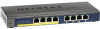
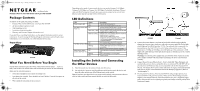
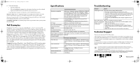
GS108P_IG_04Feb10.fm Page 1 Thursday, February 4, 2010 1:04 PM )NSTALLATION'UIDE ProSafe 8-Port 10/100/1000 Switch with 4 port PoE GS108P Package Contents In addition to this guide, the package includes: • ProSafe 8-Port 10/100/1000 Switch with 4 port PoE GS108P • AC power adapter and power cord • Wall-mounting screws • Installation Guide (this guide) • Warranty and Customer Support information card If you don't have everything listed above, see the support information card for contact information. If you're missing the Technical Support information card itself, get contact information at www.NETGEAR.com in the Customer Service area. Front View GS108P What You Need Before You Begin Decide where you want to place the switch. Find a flat horizontal surface - such as a table, desk or shelf. The switch comes with screws that you can use for wall-mounting. Make sure the selected location is: • Not in direct sunlight or near a heater or heating vent. • Not cluttered or crowded. There should be at least 2 inches (5 cm) of clear space on all sides of the switch. • Well ventilated (especially if it is in a closet). Depending on the speed of your network devices, you need a Category 3 (10 Mbps), Category 5 (100 Mbps) or Category 5e (1000 Mbps) Unshielded twisted pair Ethernet cable with RJ-45 connectors for each device you want to connect to the switch. Each Ethernet cable must be less than 328 feet (100 meters). LED Definitions LED Power (Green LED) PoE Status (Green LED Ports 1-4) PoE MAX (Amber LED) Ethernet Port Status (Green LED Ports 1-8) Status On Off On Blink slow (1.5Hz) Blink fast (10Hz) Off On Blinking Off On Blinking Off Description The GS108P is powered on. Power is not being supplied to the unit. The PoE powered device (PD) is connected and the port is supplying power successfully. The port doesn't supply power because GS108P available power is less than 7W. Indicates one of the following failures resulted in stopping power to that port: · Short circuit on PoE power circuit · PoE power demand exceeds power available · PoE current exceeds PD's classification · Thermal protection No PoE powered device (PD) connected. Less than 7W of PoE power is available. The PoE MAX LED was active in the previous two minutes. There is at least 7W of PoE power available. A link has been successfully established on the port. Port is transmitting or receiving data. There is no link. Installing the Switch and Connecting the Other Devices 1. Place the switch on a flat surface or hook onto the screws. 2. For each device, insert one end of an Ethernet cable into the port in the device and insert the other end into one of the Ethernet ports on the switch. Note: If you have more than 8 devices to connect to this switch, you must connect them to a hub or other switch and then connect that hub or switch to this switch GS108P Firewall 3. Connect the power adapter's cord into the back of the switch and then plug the adapter into a power source (such as a wall socket or power strip).The Power light should light up. Each RJ-45 jack has 2 LEDs. For each jack that is connected to a powered device, the Link LED is lit, and it flashes when activity occurs. If the connection is 10 Mbps or 100 Mbps, one LED lights up. If the connection is 1000 Mbps, both LEDs light up. If any light doesn't operate as indicated, go to the Trouble shooting section. Warning: Use only the power adapter that came with the switch. Failure to use the power adapter included with your product can damage the device and void your warranty. 4. Connect Power Devices (PDs) to Port 1 - Port 4 of GS108P. These PoE ports will automatically activate when a compatible device is connected. The GS108P will not provide power to PD devices that are not compatible with the PoE Standard IEEE 802.3af. This feature allows users to freely and safely mix legacy and standards-based PoE devices on their network without concern for damaging equipment. (Refer to "PoE Examples".) 5. First Insertion First Service. First Insertion PD Port will get higher priority. Last Insertion PD Port will get lowest priority. When an Over Power Budget situation happens, Last Insertion PD Port will be disconnected. If a port is stopped to supply power, this port will lose its original port priority and change to lowest priority when it gets power again.
-
 1
1 -
 2
2
 |
 |