Netgear GS108PP Installation Guide - Page 2
Support, Attach the Switch to a Wall, Install the Switch in a Rack, PoE Troubleshooting, Cables - manual
 |
View all Netgear GS108PP manuals
Add to My Manuals
Save this manual to your list of manuals |
Page 2 highlights
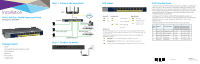
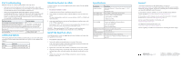
PoE Troubleshooting Here are some tips for correcting PoE problems that might occur: • Make sure that the PoE Max LED is off. If the PoE Max LED is solid amber, disconnect one or more PoE devices to prevent PoE oversubscription. Start by disconnecting the device from the highest-numbered port. • Make sure that the Ethernet cables are plugged in correctly. For each powered device (PD) that is connected to the switch, the corresponding right port LED on the switch lights solid green. If the right port LED lights solid amber, a PoE fault occurred and PoE halted because of one of the conditions that are listed in the following table. PoE Fault Condition Possible Solution A PoE-related short circuit occurred on the port. The PoE power demand of the PD exceeded the maximum level that the switch permits, which is 30.9W. The PoE current on the port exceeded the classification limit of the PD. The problem is most likely with the attached PD. Check the condition of the PD or restart the PD by disconnecting and reconnecting the PD. The PoE voltage of the port is outside the range that the switch permits. Restart the switch to see if the condition resolves itself. Cables and Speeds The following table describes the network cables that you can use for the switch connections and the speeds that these cables can support, up to 328 feet (100 meters). Speed 100 Mbps 1 Gbps Cable Type Category 5 (Cat 5) or higher rated Category 5e (Cat 5e) or higher rated Attach the Switch to a Wall To attach the switch to a wall, you need the wall-mount screws that are supplied with the switch. ¾¾ To attach the switch to a wall: 1. Locate the two mount holes on the bottom panel of the switch. 2. Mark and drill two mounting holes in the wall where you want to mount the switch. The two mounting holes must be at a precise distance of 4.27 in. (108.4 mm) from each other. 3. Insert the supplied anchors into the wall and tighten the supplied screws with a No. 2 Phillips screwdriver. Leave about 0.125 in. (4 mm) of each screw protruding from the wall so that you can insert the screws into the holes on the bottom panel. WARNING: When attaching the GS108PP switch to a wall, face the ports downward for proper ventilation and to reduce the risk of overheating. Install the Switch in a Rack To install the switch in a rack, you need the rack-mount brackets and screws that are supplied with the switch. ¾¾ To install the switch in a rack: 1. Attach the supplied mounting brackets to the side of the switch. Insert the screws provided in the product package through each bracket and into the bracket mounting holes in the switch. 2. Tighten the screws with a No. 2 Phillips screwdriver to secure each bracket. 3. Align the mounting holes in the brackets with the holes in the rack, and insert two pan-head screws with nylon washers through each bracket and into the rack. 4. Tighten the screws with a No. 2 Phillips screwdriver to secure mounting brackets to the rack. Specifications Specification Description Network interfaces Eight Gigabit Ethernet RJ-45 ports that support 1G, 100 M, and 10 M Eight PoE/PoE+ ports Power adapter input Power adapter is localized to the country of sale. Power adapter output The switch supports three power adapters: •130W: 54V @ 2.4A (included) •90W: 54V @ 1.66A •67.5W: 54V @ 1.25A Max PoE budget The maximum budget for each power adapter is: 130W: 123W PoE budget 90W: 83W PoE budget 67.5W: 60.5W PoE budget Dimensions (W x D x H) 9.3 x 4.0 x 1 in. (236 x 102 x 27 mm) Weight 1.30 lb (0.59 kg) Operating temperature 32-104°F (0-40°C) Operating humidity 10%-90% relative humidity, noncondensing Compliance FCC class A, CB, CE class A, VCCI class A, RCM class A, KC, BSMI, EAC Support Thank you for purchasing this NETGEAR product. You can visit www.netgear.com/support to register your product, get help, access the latest downloads and user manuals, and join our community. We recommend that you use only official NETGEAR support resources. Si ce produit est vendu au Canada, vous pouvez accéder à ce document en français canadien à http://downloadcenter.netgear.com/other/. (If this product is sold in Canada, you can access this document in Canadian French at http://downloadcenter.netgear.com/other/.) For the current EU Declaration of Conformity, visit http://kb.netgear.com/11621. For regulatory compliance information, visit http://www.netgear.com/about/regulatory/. See the regulatory compliance document before connecting the power supply. NETGEAR INTL LTD Building 3, University Technology Centre Curraheen Road, Cork, Ireland © NETGEAR, Inc., NETGEAR and the NETGEAR Logo are trademarks of NETGEAR, Inc. Any non‑NETGEAR trademarks are used for reference purposes only.
-
 1
1 -
 2
2
 |
 |