Netgear GS110TP GS110TP Hardware Installation Guide - Page 19
Step 3: Checking the Installation, Step 4: Connecting Devices to the Switch, Desktop PC - prosafe
 |
UPC - 606449069129
View all Netgear GS110TP manuals
Add to My Manuals
Save this manual to your list of manuals |
Page 19 highlights
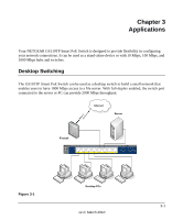
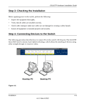
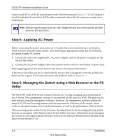
Step 3: Checking the Installation GS110TP Hardware Installation Guide Before applying power to the switch, perform the following: • Inspect the equipment thoroughly. • Verify that all cables are installed correctly. • Check cable routing to make sure cables are not damaged or creating a safety hazard. • Ensure all equipment is mounted properly and securely. Step 4: Connecting Devices to the Switch The following procedure describes how to connect PCs to the switch's RJ-45 ports. The GS110TP Smart PoE Switch contains Auto Uplink technology, which allows the attaching of devices using either straight-through or crossover cables. PoE Max Link/Act PoE Link/Act Mode Green=Link at 1000M Yellow=Link at 100M/10M Blink=ACT PoE Mode Green=PoE Powered Yellow=PoE Fault PoE Ports PROSAFE GS110TP Link/Act 9F Link/Act 10F ` ` Figure 4-1 Desktop PC Desktop PC Installation 4-3 v1.0, March 2010
-
 1
1 -
2
-
3
-
4
-
5
-
6
-
7
-
8
-
9
-
10
-
11
-
12
-
13
-
 14
14 -
 15
15 -
 16
16 -
 17
17 -
 18
18 -
 19
19 -
 20
20 -
 21
21 -
 22
22 -
 23
23 -
 24
24 -
25
-
26
-
27
-
28
-
29
-
30
-
31
-
32
 |
 |