Netgear GS516TNA GS516T Reference Manual - Page 18
Installing the Switch on a Flat Surface, Installing the Switch in a Rack, Connecting Devices to
 |
View all Netgear GS516TNA manuals
Add to My Manuals
Save this manual to your list of manuals |
Page 18 highlights
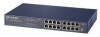
• The Installation Guide • Support Information Card Installing the Switch on a Flat Surface To install the switch on a flat surface, be sure to attach the rubber footpads to the bottom of the switch. Installing the Switch in a Rack Refer to Figure 4-1 when installing the switch in a rack. 100/1000 Mbps Copper Gigabit Switch Power Ethernet MODEL GS516T Figure 4-1. Attaching Mounting Brackets Connecting Devices to the Switch To connect the switch: 1. Connect the devices to the network ports on the switch, using Category 5 (Cat5) or Category 5e (Cat5e) UTP cable. Note: Ethernet specifications limit the cable length between your PC or server and the switch to 100 m. 2. Connect one end of the AC power adapter cable to the power receptacle on the rear panel of the switch and the other end of the power adapter cable to the wall outlet. installation 4-2
-
 1
1 -
2
-
3
-
4
-
5
-
6
-
7
-
8
-
9
-
10
-
11
-
12
-
 13
13 -
 14
14 -
 15
15 -
 16
16 -
 17
17 -
 18
18 -
 19
19 -
 20
20 -
 21
21 -
 22
22 -
 23
23 -
24
-
25
-
26
-
27
-
28
-
29
-
30
-
31
-
32
-
33
-
34
 |
 |
