Netgear GS752TPS GS7xxTS-TPS Hardware Installation Guide - Page 15
GS752TS Front-Panel and Back-Panel Configuration
 |
View all Netgear GS752TPS manuals
Add to My Manuals
Save this manual to your list of manuals |
Page 15 highlights
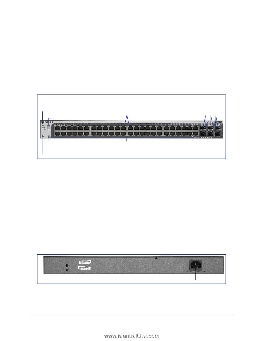
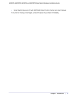
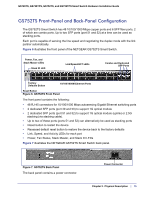
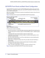
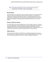
GS728TS, GS728TPS, GS752TS, and GS752TPS Smart Switch Hardware Installation Guide GS752TS Front-Panel and Back-Panel Configuration The GS752TS Smart Switch has 48 10/100/1000 Mbps copper ports and 6 SFP fiber ports, 2 of which are combo ports. Up to two SFP ports (port 51 and 52) at a time can be used as stacking ports. Each port is capable of sensing the line speed and negotiating the duplex mode with the link partner automatically. Figure 6 illustrates the front panel of the NETGEAR GS752TS Smart Switch. Power, Fan, and Stack Master LEDs Stack ID LED Link/Speed/ACT LEDs Combo and Dedicated SFP Ports Factory Defaults Button 10/100/1000M Ethernet Ports Reset Button Figure 6. GS752TS Front Panel The front panel contains the following: • 48 RJ-45 connectors for 10/100/1000 Mbps autosensing Gigabit Ethernet switching ports • 2 dedicated SFP ports (port 49 and 50) to support 1G optical module • 2 dedicated SFP ports (port 51 and 52) to support 1G optical module (uplink) or 2.5G stacking (via stacking cable). • Up to two of these ports (ports 51 and 52) can alternatively be used as stacking ports • Reset button to restart the device • Recessed default reset button to restore the device back to the factory defaults • Link, Speed, and Activity LEDs for each port • Power, Fan Status, Stack Master, and Stack ID LEDs Figure 7 illustrates the NETGEAR GS752TS Smart Switch back panel. Figure 7. GS752TS Back Panel The back panel contains a power connector. Power Connector Chapter 2. Physical Description | 15
-
 1
1 -
2
-
3
-
4
-
5
-
6
-
7
-
8
-
9
-
 10
10 -
 11
11 -
 12
12 -
 13
13 -
 14
14 -
 15
15 -
 16
16 -
 17
17 -
 18
18 -
 19
19 -
 20
20 -
21
-
22
-
23
-
24
-
25
-
26
-
27
-
28
-
29
-
30
-
31
-
32
-
33
-
34
-
35
-
36
-
37
-
38
-
39
-
40
-
41
-
42
 |
 |