Netgear GS752TPS GS7xxTS-TPS Software Admin Manual - Page 320
MSTP Example Configuration, Configuration Name
 |
View all Netgear GS752TPS manuals
Add to My Manuals
Save this manual to your list of manuals |
Page 320 highlights
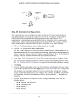
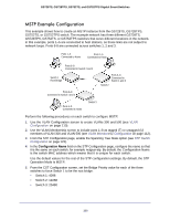
GS728TS, GS728TPS, GS752TS, and GS752TPS Gigabit Smart Switches MSTP Example Configuration This example shows how to create an MSTP instance from the GS728TS, GS728TPS, GS752TS, or GS752TPS switch. The example network has three different GS728TS, GS728TPS, GS752TS, or GS752TPS switches that serve different locations in the network. In this example, ports 1-5 are connected to host stations, so those links are not subject to network loops. Ports 6-8 are connected across switches 1, 2 and 3. Ports 1-5 Connected to Hosts Ports 1-5 Connected to Hosts Ports 6-8 Connected to Switch 2 and 3 Switch 1 Root Bridge Ports 6-8 Connected to Switch 1 and 3 Switch 2 Ports 6-8 Connected to Switch 1 and 2 Ports 1-5 Connected to Hosts Switch 3 Perform the following procedures on each switch to configure MSTP: 1. Use the VLAN Configuration screen to create VLANs 300 and 500 (see VLAN Configuration on page 110). 2. Use the VLAN Membership screen to include ports 1-8 as tagged (T) or untagged (U) members of VLAN 300 and VLAN 500 (see VLAN Membership Configuration on page 112). 3. From the STP Configuration page, enable the Spanning Tree State option (see STP Switch Configuration on page 123). 4. In the Configuration Name field on the STP Configuration page, configure the name so that it is the same on each switch, for example netgear-stp. By default, the Configuration Name is the switch MAC address which means that it is unique for each switch. Use the default values for the rest of the STP configuration settings. By default, the STP Operation Mode is MSTP. 5. From the CST Configuration screen, set the Bridge Priority value for each of the three switches to force Switch 1 to be the root bridge: • Switch 1: 4096 • Switch 2: 12288 • Switch 3: 20480 320
-
 1
1 -
2
-
3
-
4
-
5
-
6
-
7
-
8
-
9
-
10
-
11
-
12
-
13
-
14
-
15
-
16
-
17
-
18
-
19
-
20
-
21
-
22
-
23
-
24
-
25
-
26
-
27
-
28
-
29
-
30
-
31
-
32
-
33
-
34
-
35
-
36
-
37
-
38
-
39
-
40
-
41
-
42
-
43
-
44
-
45
-
46
-
47
-
48
-
49
-
50
-
51
-
52
-
53
-
54
-
55
-
56
-
57
-
58
-
59
-
60
-
61
-
62
-
63
-
64
-
65
-
66
-
67
-
68
-
69
-
70
-
71
-
72
-
73
-
74
-
75
-
76
-
77
-
78
-
79
-
80
-
81
-
82
-
83
-
84
-
85
-
86
-
87
-
88
-
89
-
90
-
91
-
92
-
93
-
94
-
95
-
96
-
97
-
98
-
99
-
100
-
101
-
102
-
103
-
104
-
105
-
106
-
107
-
108
-
109
-
110
-
111
-
112
-
113
-
114
-
115
-
116
-
117
-
118
-
119
-
120
-
121
-
122
-
123
-
124
-
125
-
126
-
127
-
128
-
129
-
130
-
131
-
132
-
133
-
134
-
135
-
136
-
137
-
138
-
139
-
140
-
141
-
142
-
143
-
144
-
145
-
146
-
147
-
148
-
149
-
150
-
151
-
152
-
153
-
154
-
155
-
156
-
157
-
158
-
159
-
160
-
161
-
162
-
163
-
164
-
165
-
166
-
167
-
168
-
169
-
170
-
171
-
172
-
173
-
174
-
175
-
176
-
177
-
178
-
179
-
180
-
181
-
182
-
183
-
184
-
185
-
186
-
187
-
188
-
189
-
190
-
191
-
192
-
193
-
194
-
195
-
196
-
197
-
198
-
199
-
200
-
201
-
202
-
203
-
204
-
205
-
206
-
207
-
208
-
209
-
210
-
211
-
212
-
213
-
214
-
215
-
216
-
217
-
218
-
219
-
220
-
221
-
222
-
223
-
224
-
225
-
226
-
227
-
228
-
229
-
230
-
231
-
232
-
233
-
234
-
235
-
236
-
237
-
238
-
239
-
240
-
241
-
242
-
243
-
244
-
245
-
246
-
247
-
248
-
249
-
250
-
251
-
252
-
253
-
254
-
255
-
256
-
257
-
258
-
259
-
260
-
261
-
262
-
263
-
264
-
265
-
266
-
267
-
268
-
269
-
270
-
271
-
272
-
273
-
274
-
275
-
276
-
277
-
278
-
279
-
280
-
281
-
282
-
283
-
284
-
285
-
286
-
287
-
288
-
289
-
290
-
291
-
292
-
293
-
294
-
295
-
296
-
297
-
298
-
299
-
300
-
301
-
302
-
303
-
304
-
305
-
306
-
307
-
308
-
309
-
310
-
311
-
312
-
313
-
314
-
 315
315 -
 316
316 -
 317
317 -
 318
318 -
 319
319 -
 320
320 -
 321
321 -
 322
322 -
 323
323 -
 324
324 -
 325
325 -
326
-
327
-
328
-
329
 |
 |
