Netgear GSM7224v1 GSM7212 Hardware manual - Page 23
Connecting Equipment to the Switch, RJ-45 Ports, Gigabit Module Bay
 |
View all Netgear GSM7224v1 manuals
Add to My Manuals
Save this manual to your list of manuals |
Page 23 highlights
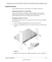
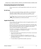
Managed Layer 2 Switches GSM7212, GSM7224, and GSM7248 Hardware Installation Guide Connecting Equipment to the Switch You can connect devices, an SPF Gigabit Ethernet module, and a console to the switch. RJ-45 Ports The switch uses Auto Uplink technology, which enables you to attach devices using either straight-through or crossover cables. Use a Category 5 (Cat5) unshielded twisted-pair (UTP) cable terminated with an RJ-45 connector. Note: Ethernet specifications limit the cable length between the switch and the attached device to 328 feet (100 meters). Gigabit Module Bay You can install an SFP Gigabit Ethernet module in the gigabit module bays. SFP modules are sold separately. Four ports on the switch can be used for either STP (RJ-45) or SFP (fiber) cable. However, both port types cannot be used at the same time. The switch selects the first connected interface. If both connectors are plugged, the SFP interface operates normally and disables the copper interface. The SFP bay accommodates a standard SFP module with an LC connector that is compatible with the IEEE 802.3z 1000BASE-SX standard. To install an SFP module: 1. Insert the SFP module into the SFP module bay. Press firmly to ensure that the module seats into the connector. 2. After the switch has been configured for management, use one of the management interfaces (Web browser or console interface) to configure the port with the SFP module. 3. To install additional Gigabit Ethernet modules, repeat step 1. Hardware Installation 3-7 v1.0, March 2006
-
 1
1 -
2
-
3
-
4
-
5
-
6
-
7
-
8
-
9
-
10
-
11
-
12
-
13
-
14
-
15
-
16
-
17
-
 18
18 -
 19
19 -
 20
20 -
 21
21 -
 22
22 -
 23
23 -
 24
24 -
 25
25 -
 26
26 -
 27
27 -
 28
28 -
29
-
30
-
31
-
32
-
33
-
34
-
35
-
36
-
37
-
38
 |
 |