Netgear GSM7248v1 GSM7212 Hardware manual - Page 21
Install the Switch, Installing the Switch on a Flat Surface
 |
View all Netgear GSM7248v1 manuals
Add to My Manuals
Save this manual to your list of manuals |
Page 21 highlights
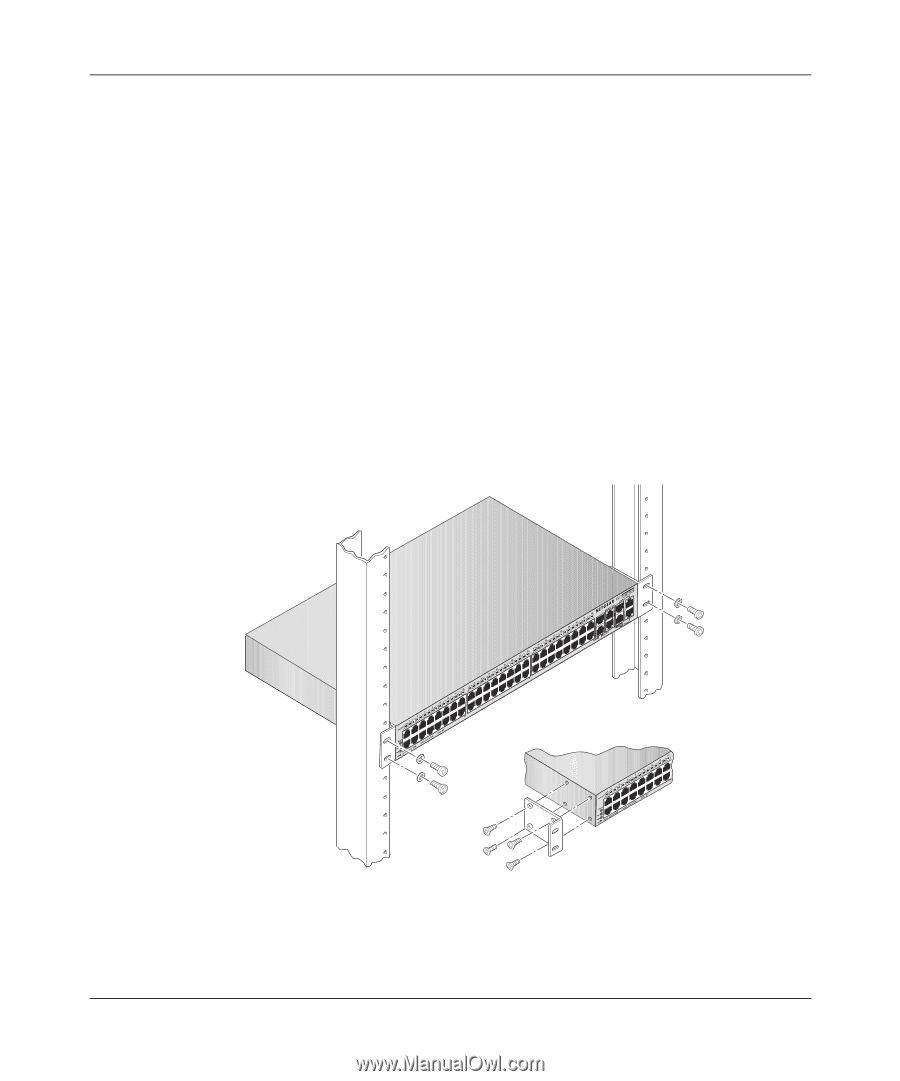
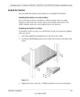
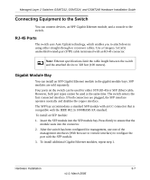
Managed Layer 2 Switches GSM7212, GSM7224, and GSM7248 Hardware Installation Guide Install the Switch You can install the switch on a flat surface or in a standard 19-inch rack. Installing the Switch on a Flat Surface The switch ships with four self-adhesive rubber footpads. Stick one rubber footpad on each of the four concave spaces on the bottom of the switch. The rubber footpads cushion the switch against shock and vibrations. Installing the Switch in a Rack To install the switch in a rack, you will need the 19-inch rack-mount kit supplied with your switch. 1. Attach the supplied mounting brackets to the side of the switch. 2. Use the provided Phillips head screws to fasten the brackets to the sides of the switch. Figure 3-1 3. Tighten the screws with a No. 1 Phillips screwdriver to secure each bracket. Hardware Installation 3-5 v1.0, March 2006
-
 1
1 -
2
-
3
-
4
-
5
-
6
-
7
-
8
-
9
-
10
-
11
-
12
-
13
-
14
-
15
-
 16
16 -
 17
17 -
 18
18 -
 19
19 -
 20
20 -
 21
21 -
 22
22 -
 23
23 -
 24
24 -
 25
25 -
 26
26 -
27
-
28
-
29
-
30
-
31
-
32
-
33
-
34
-
35
-
36
-
37
-
38
 |
 |