Netgear GSM7252PS GSM72xxPS and GSM73xxSv2 Series Managed Switch Hardware Inst - Page 11
GSM7328S Front Panel and LEDs
 |
UPC - 606449071665
View all Netgear GSM7252PS manuals
Add to My Manuals
Save this manual to your list of manuals |
Page 11 highlights
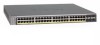
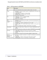
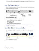
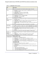
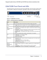
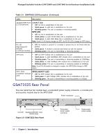
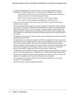
Managed Stackable Switches GSM7200PS and GSM7300S Series Hardware Installation Guide GSM7328S Front Panel and LEDs The following figure shows the front panel of the GSM7328S. The front panel contains LEDs, a Reset button, a USB port, RJ-45 jacks, copper/fiber combo ports, and 10G SFP+ ports. LEDs Reset button Figure 1-5 GSM7328S Front Panel Table 1-5. LED Descriptions for GSM7328S RJ-45 jacks Combo Ports SFP+ Ports LED Description ID This is the stack member ID (1-8) that the software assigns to the switch. Master • Green: Switch acts as a master unit in a stack of GSM7300S series switches. • Off: Switch acts as a slave unit in a stack of GSM7300S series switches. RPS (redundant power supply) • Solid green: The redundant power supply is connected (and using the power module's power). • Solid yellow: The power module power has failed or been disconnected, but the redundant power supply is providing power to the switch. • Blinking yellow: The redundant power supply unit is present, but the power has failed. • Off: The redundant power supply is disconnected or not present. Fan • Solid green: Fan operating normally. • Solid yellow: Fan has failed • Off: No fan detected. PWR (power) • Solid green: Power module is present and supplies power to the switch and is working normally. • Solid yellow: System is in boot-up stage. • Blinking yellow: POS/CPU system has failed. • Off: Power is disconnected. M1, M2 High-Speed I/O Modules (1 LED per module) • Off: No module is present or a module is present but is not linked with the system. • Solid green: A module is present and linked up with the system. • Blinking green: The port is transmitting or receiving packets. Chapter 1: Introduction | 11
-
 1
1 -
2
-
3
-
4
-
5
-
 6
6 -
 7
7 -
 8
8 -
 9
9 -
 10
10 -
 11
11 -
 12
12 -
 13
13 -
 14
14 -
 15
15 -
 16
16 -
17
-
18
-
19
-
20
-
21
-
22
-
23
-
24
-
25
-
26
-
27
-
28
-
29
-
30
-
31
-
32
-
33
-
34
-
35
-
36
-
37
-
38
-
39
 |
 |
