Netgear GSM7328FS GSM7352S Hardware manual - Page 12
GSM7328S Rear Panel, GSM7352S Front Panel and LEDs
 |
UPC - 606449050790
View all Netgear GSM7328FS manuals
Add to My Manuals
Save this manual to your list of manuals |
Page 12 highlights
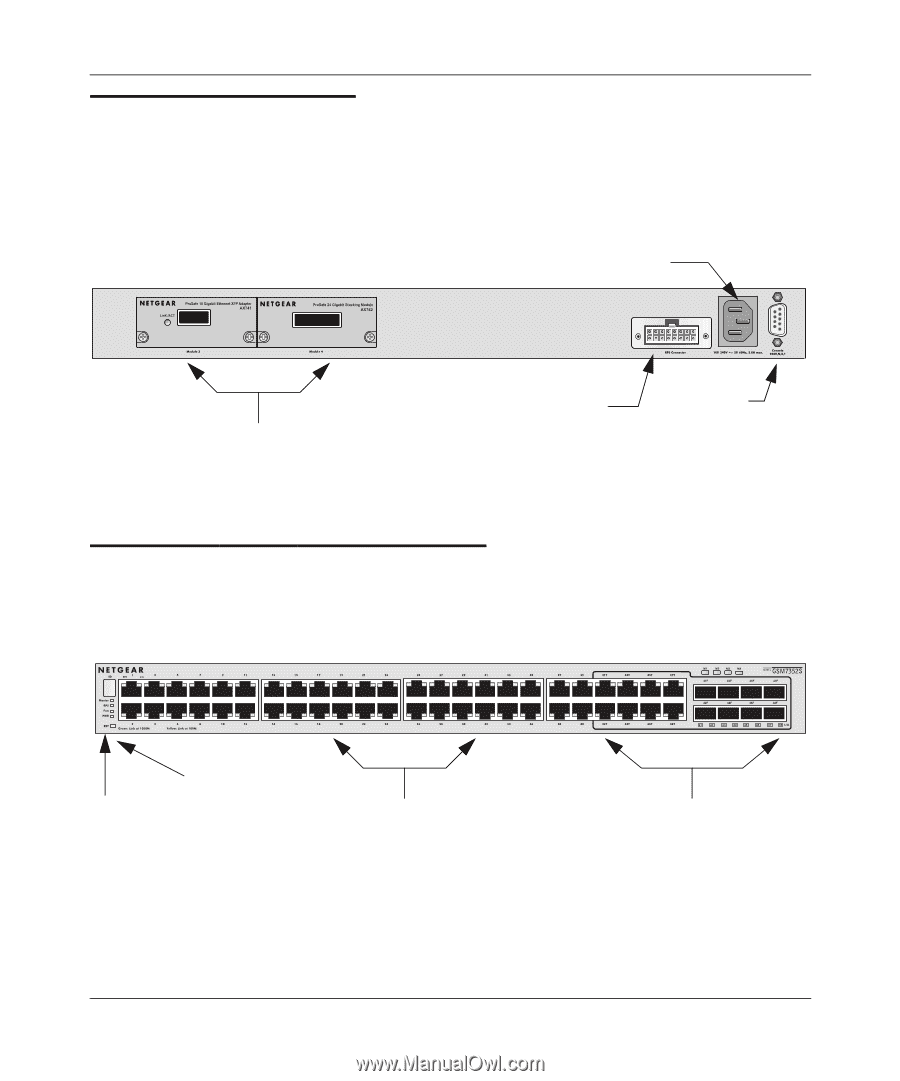
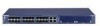
Managed Stackable Layer 3 Switches GSM7328S and GSM7352S Hardware Installation Guide GSM7328S Rear Panel The rear panel has two module bays, a console port, redundant power supply connector, and a standard AC power receptacle for the supplied power cord. The module bays support any combination of either the ProSafe 10-Gigabit Ethernet XFP Adapter (AX741) or the ProSafe 24-Gigabit Stackable Module (AX742). Power receptacle Figure 2-2 Stacking/XFP module bays Redundant power supply connector Console GSM7352S Front Panel and LEDs The figure below shows the front panel of the GSM7352S. The front panel contains LEDs, a RST (reset) button, RJ-45 jacks, and copper/fiber combo ports. 1 RST LEDs (reset button) Figure 2-3 RJ-45 jacks Copper/fiber combo ports 2-4 Introduction v1.0, March 2006
-
 1
1 -
2
-
3
-
4
-
5
-
6
-
 7
7 -
 8
8 -
 9
9 -
 10
10 -
 11
11 -
 12
12 -
 13
13 -
 14
14 -
 15
15 -
 16
16 -
 17
17 -
18
-
19
-
20
-
21
-
22
-
23
-
24
-
25
-
26
-
27
-
28
-
29
-
30
-
31
-
32
-
33
-
34
-
35
-
36
-
37
-
38
-
39
-
40
 |
 |