Netgear GSM7328FS GSM7328S, GSM7352S and GSM7328FS Hardware Installation Guide
Netgear GSM7328FS - ProSafe Switch - Stackable Manual
 |
UPC - 606449050790
View all Netgear GSM7328FS manuals
Add to My Manuals
Save this manual to your list of manuals |
Netgear GSM7328FS manual content summary:
- Netgear GSM7328FS | GSM7328S, GSM7352S and GSM7328FS Hardware Installation Guide - Page 1
Managed Stackable Layer 3 Switches GSM7328S, GSM7352S and GSM7328FS Hardware Installation Guide NETGEAR, Inc. 4500 Great America Parkway Santa Clara, CA 95054 USA 202-10255-01 February 2007 - Netgear GSM7328FS | GSM7328S, GSM7352S and GSM7328FS Hardware Installation Guide - Page 2
. Please refer to the notes in the operating instructions. It is hereby certified that the NETGEAR ProSafe™ 24-Port 10/100/1000 L3 managed Stackable Switch with 4 10 Gigabit I/O Slots GSM7328S has been suppressed in accordance with the conditions set out in the BMPT-AmtsblVfg 243/1991 and Vfg - Netgear GSM7328FS | GSM7328S, GSM7352S and GSM7328FS Hardware Installation Guide - Page 3
in accordance with the instructions, may cause harmful the equipment off and on, the user is encouraged to try to correct the Canada. EN 55 022 Declaration of Conformance This is to certify that the NETGEAR ProSafe™ 24-Port 10/100/1000 L3 managed Stackable Switch with 4 10 Gigabit I/ O Slots GSM7328S - Netgear GSM7328FS | GSM7328S, GSM7352S and GSM7328FS Hardware Installation Guide - Page 4
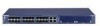
switch • ProSafe™ 24-Port 10/100/1000 L3 managed Stackable Switch with 4 10 Gigabit I/O Slots GSM7328S • ProSafe™ 48-Port 10/100/1000 L3 managed Stackable Switch with 4 10 Gigabit I/O Slots GSM7352S • ProSafe™ 24 Fiber SFP Gigabit Layer 3 managed Stackable Switch with 4 10-Gigabit Slots GSM7328FS - Netgear GSM7328FS | GSM7328S, GSM7352S and GSM7328FS Hardware Installation Guide - Page 5
1-2 How to Print this Manual 1-3 Revision History ...1-4 Chapter 2 Introduction GSM7328S Front Panel and LEDs 2-1 GSM7328S Rear Panel 2-4 GSM7352S Front Panel and LEDs 2-4 GSM7352S Rear Panel 2-6 GSM7328FS Front Panel and LEDs 2-7 GSM7328FS Rear Panel 2-9 Safety Instructions ...2-10 Chapter - Netgear GSM7328FS | GSM7328S, GSM7352S and GSM7328FS Hardware Installation Guide - Page 6
Connecting Equipment to the Switch 3-10 RJ-45 Ports ...3-10 Connecting a Console to the Switch 3-11 Chapter 4 Troubleshooting Troubleshooting Chart 4-1 Additional Troubleshooting Suggestions 4-2 Appendix A Technical Specifications Appendix B Default Configuration Settings vi v1.0, February 2007 - Netgear GSM7328FS | GSM7328S, GSM7352S and GSM7328FS Hardware Installation Guide - Page 7
This Manual The Managed Stackable Layer 3 Switches GSM7328S, GSM7352S and GSM7328FS Hardware Installation Guide describes installation and basic troubleshoting for the NETGEAR® GSM7328S and GSM7352S switches. Audience, Conventions, Formats, and Scope This information in this guide is intended - Netgear GSM7328FS | GSM7328S, GSM7352S and GSM7328FS Hardware Installation Guide - Page 8
specifications : Table 1-2. Manual Scope Product Version Manual Publication Date • ProSafe™ 24-Port 10/100/1000 L3 managed Stackable Switch with 4 10 Gigabit I/O Slots GSM7328S • ProSafe™ 48-Port 10/100/1000 L3 managed Stackable Switch with 4 10 Gigabit I/O Slots GSM7352S • ProSafe™ 24 Fiber SFP - Netgear GSM7328FS | GSM7328S, GSM7352S and GSM7328FS Hardware Installation Guide - Page 9
Managed Stackable Layer 3 Switches GSM7328S, GSM7352S and GSM7328FS Hardware Instal- How to Print this Manual To print this manual, you can choose one of the following options, according to your needs. • Printing a Page from HTML. Each page in the HTML version of the manual is dedicated to a major - Netgear GSM7328FS | GSM7328S, GSM7352S and GSM7328FS Hardware Installation Guide - Page 10
Layer 3 Switches GSM7328S, GSM7352S and GSM7328FS Hardware Instal- Revision History Part Number Version Publication Date Description 201-10813-01 1.0 202-10255-01 1.0 March 2006 February 2007 Document Created. Added description of GSM7328FS switch. 1-4 About This Manual v1.0, February - Netgear GSM7328FS | GSM7328S, GSM7352S and GSM7328FS Hardware Installation Guide - Page 11
and basic troubleshooting for the following NETGEAR switches: • ProSafe™ 24-Port 10/100/1000 L3 managed Stackable Switch with 4 10 Gigabit I/O Slots GSM7328S • ProSafe™ 48-Port 10/100/1000 L3 managed Stackable Switch with 4 10 Gigabit I/O Slots GSM7352S • ProSafe™ 24 Fiber SFP Gigabit Layer - Netgear GSM7328FS | GSM7328S, GSM7352S and GSM7328FS Hardware Installation Guide - Page 12
Managed Stackable Layer 3 Switches GSM7328S, GSM7352S and GSM7328FS Hardware Instal1 LEDs RST RJ-45 jacks (reset button) Copper/fiber combo ports Stacking/XFP module bays Figure 2-1 The following table describes the LEDs on the front panel of the switch. Table 2-1. LED Descriptions for - Netgear GSM7328FS | GSM7328S, GSM7352S and GSM7328FS Hardware Installation Guide - Page 13
on the port. • Solid yellow: A valid 100 Mbps link is established on the port. • Solid green: A valid 1000 Mbps link is established on the port. Note: If port 21-24 media is changed to SFP, the RJ-45 LEDs l change to OFF status. SFP Ports (1Link/ACT LED per port) • Off: No SFP module link - Netgear GSM7328FS | GSM7328S, GSM7352S and GSM7328FS Hardware Installation Guide - Page 14
GSM7328S, GSM7352S and GSM7328FS Hardware Instal- GSM7328S Rear Panel The rear panel has two module bays, a console port, redundant power supply connector, and a standard AC power receptacle for the supplied power cord. The module bays support any combination of either the ProSafe 10-Gigabit - Netgear GSM7328FS | GSM7328S, GSM7352S and GSM7328FS Hardware Installation Guide - Page 15
3 Switches GSM7328S, GSM7352S and GSM7328FS Hardware Instal- The table below describes the GSM7352S LEDs on the front of the switch. Table 2-2. GSM7352S LED Description LED Description ID This is the stack member ID (1-8) that the software assigns to the switch. Master • Green: The switch - Netgear GSM7328FS | GSM7328S, GSM7352S and GSM7328FS Hardware Installation Guide - Page 16
module bays, a redundant power supply connector, a console port, and a standard AC power receptacle for the supplied power cord. The module bays support any combination of either the ProSafe 10-Gigabit Ethernet XFP Adapter (AX741) or the ProSafe 24-Gigabit Stackable Module (AX742). See "High-Speed - Netgear GSM7328FS | GSM7328S, GSM7352S and GSM7328FS Hardware Installation Guide - Page 17
the front panel of the GSM7328FS. The front panel contains LEDs, a RST (reset) button, RJ-45 jacks, copper/fiber combo ports, and two module bays. The module bays support any combination of either the ProSafe 24-Gigabit Stackable Module (AX742) or the ProSafe 10-Gigabit Ethernet XFP Adapter (AX741 - Netgear GSM7328FS | GSM7328S, GSM7352S and GSM7328FS Hardware Installation Guide - Page 18
Descriptions for GSM7328FS LED Description Power /Status LED • Solid Green: Power is supplied to the switch and it is operating normally • Solid Yellow: POST in progress Blinking Yellow: POST / CPU system / Internal Power Supply failure • Off: Power is disconnected. 4-10/100/1000M Ports two LED - Netgear GSM7328FS | GSM7328S, GSM7352S and GSM7328FS Hardware Installation Guide - Page 19
. • Off: NETGEAR RPS Bank Disconnected. GSM7328FS Rear Panel The rear panel has two module bays, a console port, redundant power supply connector, and a standard AC power receptacle for the supplied power cord. The module bays support any combination of either the ProSafe 10-Gigabit Ethernet XFP - Netgear GSM7328FS | GSM7328S, GSM7352S and GSM7328FS Hardware Installation Guide - Page 20
Switches GSM7328S, GSM7352S and GSM7328FS Hardware Instal- Safety Instructions service markings. - Do not service any product except as explained in your system documentation. see the appropriate section in your troubleshooting guide or contact your trained service provider. • Do not push any - Netgear GSM7328FS | GSM7328S, GSM7352S and GSM7328FS Hardware Installation Guide - Page 21
Switches GSM7328S, GSM7352S and GSM7328FS Hardware Instal- • To help avoid damaging your system, be sure that the voltage selection switch (if provided) on the power supply is set Do not modify power cables or plugs. Consult a licensed electrician or your power company for site modifications. • - Netgear GSM7328FS | GSM7328S, GSM7352S and GSM7328FS Hardware Installation Guide - Page 22
Managed Stackable Layer 3 Switches GSM7328S, GSM7352S and GSM7328FS Hardware Instal- 2-12 v1.0, February 2007 Introduction - Netgear GSM7328FS | GSM7328S, GSM7352S and GSM7328FS Hardware Installation Guide - Page 23
caps for the SFP sockets • Rack-mounting kit • Null-modem serial cable (RS-232) with 9-pin connectors • NETGEAR CD: The CD contains - Configuration software - Documentation including the Command Line Interface Reference for the ProSafe 7300S Series Layer-3 Stackable Switches, the NETGEAR 7000 Series - Netgear GSM7328FS | GSM7328S, GSM7352S and GSM7328FS Hardware Installation Guide - Page 24
Managed Stackable Layer 3 Switches GSM7328S, GSM7352S and GSM7328FS Hardware Instal- Protecting Against Electrostatic Discharge . You can do so by periodically touching an unpainted metal surface on the switch. You can also take the following steps to prevent damage from electrostatic discharge - Netgear GSM7328FS | GSM7328S, GSM7352S and GSM7328FS Hardware Installation Guide - Page 25
Managed Stackable Layer 3 Switches GSM7328S, GSM7352S and GSM7328FS Hardware Instal- 4. Make sure that all items are present. See "Package Contents" on page 3-1. Note: If any item is found missing or damaged, contact your local NETGEAR reseller for replacement. 5. Inspect the products and - Netgear GSM7328FS | GSM7328S, GSM7352S and GSM7328FS Hardware Installation Guide - Page 26
Managed Stackable Layer 3 Switches GSM7328S, GSM7352S and GSM7328FS Hardware Instal- Select a Location The switch can be mounted in a standard 19-inch (48.26-centimeter) rack, wallmounted, or left freestanding (placed on a tabletop). The site where you install the switch may greatly affect its - Netgear GSM7328FS | GSM7328S, GSM7352S and GSM7328FS Hardware Installation Guide - Page 27
Managed Stackable Layer 3 Switches GSM7328S, GSM7352S and GSM7328FS Hardware Instal- Install the Switch You can install the switch on a flat surface or in a standard 19-inch rack. Installing the Switch on a Flat Surface The switch ships with four self-adhesive rubber footpads. Stick one rubber - Netgear GSM7328FS | GSM7328S, GSM7352S and GSM7328FS Hardware Installation Guide - Page 28
Managed Stackable Layer 3 Switches GSM7328S, GSM7352S and GSM7328FS Hardware Instal- 4. Align the bracket and rack holes. Use two pan-head screws with nylon washers to fasten each bracket to the rack. 5. Tighten the screws with a No. 2 Phillips screwdriver to secure the switch in the rack. Check the - Netgear GSM7328FS | GSM7328S, GSM7352S and GSM7328FS Hardware Installation Guide - Page 29
Layer 3 Switches GSM7328S, GSM7352S and GSM7328FS Hardware Instal- High-Speed I/O Module Bays The High-Speed I/O Module Bays can be used for inter-switch stacking or to install XFP 10-Gigabit Ethernet modules. If you want to do both, you can stack the switch using two 24-Gigabit Stackable Modules - Netgear GSM7328FS | GSM7328S, GSM7352S and GSM7328FS Hardware Installation Guide - Page 30
Layer 3 Switches GSM7328S, GSM7352S and GSM7328FS Hardware Instal- 2. To install additional Gigabit Ethernet modules, repeat step 1. High-Speed I/O Module Installation The High-Speed I/O Module Bays support ProSafe 10-Gigabit Ethernet XFP Adapter (AX741) or ProSafe 24-Gigabit Stackable Modules - Netgear GSM7328FS | GSM7328S, GSM7352S and GSM7328FS Hardware Installation Guide - Page 31
Layer 3 Switches GSM7328S, GSM7352S and GSM7328FS Hardware Instal- Stacking You can connect up to eight switches to form a stack with a single management IP address. The switches automatically select a master unit. Once the master is selected, you can use its console to manage all the switches in - Netgear GSM7328FS | GSM7328S, GSM7352S and GSM7328FS Hardware Installation Guide - Page 32
plate and connect the RPS unit to the switch. After all connections are completed, apply power to the switch. Connecting Equipment to the Switch You can connect devices, a Gigabit Ethernet module, and/or a console to the switch. RJ-45 Ports The switch uses Auto Uplink technology, which enables you - Netgear GSM7328FS | GSM7328S, GSM7352S and GSM7328FS Hardware Installation Guide - Page 33
Managed Stackable Layer 3 Switches GSM7328S, GSM7352S and GSM7328FS Hardware Instal- Connecting a Console to the Switch After you install the switch and apply power, you can connect to it with a terminal or workstation. You can use the Command Line Interface (CLI) to identify the IP address. If you - Netgear GSM7328FS | GSM7328S, GSM7352S and GSM7328FS Hardware Installation Guide - Page 34
GSM7328S, GSM7352S and GSM7328FS Hardware Instal- After you connect a console to the switch, you will need to configure the switch. The following documents are provided for this purpose: • Quick Installation Guide: Explains basic setup and configuration (provided as both a print document and in PDF - Netgear GSM7328FS | GSM7328S, GSM7352S and GSM7328FS Hardware Installation Guide - Page 35
comply with Ethernet specifications. See Appendix A. Check for a defective adapter card, cable, or port by testing it in an alternate environment where all products are functioning. File transfer is slow or performance degradation is a problem. Half- or full-duplex setting on the switch and the - Netgear GSM7328FS | GSM7328S, GSM7352S and GSM7328FS Hardware Installation Guide - Page 36
integrity of the switch by resetting the switch. To reset the switch, use the Tools> Reset command or remove AC power from the switch and then reapply AC power. If the problem continues, contact NETGEAR technical support. • Auto-Negotiation: The copper 10/100/1000 Mbps ports negotiate the correct - Netgear GSM7328FS | GSM7328S, GSM7352S and GSM7328FS Hardware Installation Guide - Page 37
Technical Specifications Feature IEEE Network Protocol and Standards compatibility Switch management GSM7328S GSM7352S 802.3 10BASE-T 802.3u 100BASE-TX 802.3z 1000BASE-SX 802.3z 1000BASE-LX 802.3ab 1000BASE-T 802.3ae 10000BASE-LR 802.3ae 10000BASE-SR 802.3x flow control • Port mirroring support - Netgear GSM7328FS | GSM7328S, GSM7352S and GSM7328FS Hardware Installation Guide - Page 38
SFP modules • 4 I/O modules for either 10Gbps XFP or stacking connection • RS-232 Console Port Bandwidth 144 Gbps 196 Gbps 144 Gbps Address 8K MAC addresses per system database size 10/100/1000 8MB embedded memory for Max support 0.75-MB buffer 8MB embedded memory for buffer memory 24 ports - Netgear GSM7328FS | GSM7328S, GSM7352S and GSM7328FS Hardware Installation Guide - Page 39
Switches GSM7328S, GSM7352S and GSM7328FS Hardware Instal- Table A-1. Technical Specifications (continued) Feature GSM7328S GSM7352S GSM7328FS Heat dissipation: 18.99 Btu/hr Power consumption 80 W maximum 100- 108 W maximum 100- 80 W maximum 100- 240VAC, 50-60 Hz universal 240VAC, 50-60 Hz - Netgear GSM7328FS | GSM7328S, GSM7352S and GSM7328FS Hardware Installation Guide - Page 40
Managed Stackable Layer 3 Switches GSM7328S, GSM7352S and GSM7328FS Hardware Instal- A-4 Technical Specifications v1.0, February 2007 - Netgear GSM7328FS | GSM7328S, GSM7352S and GSM7328FS Hardware Installation Guide - Page 41
provides the default settings for the NETGEAR Model GSM7328S, GSM7352S, and GSM7328FS switches. Table B-1. Default Configuration Settings Features Default Setting Port speed Auto-negotiation Port duplex Auto-negotiation Flow control (half duplex) Enabled Flow control (full duplex) Disabled - Netgear GSM7328FS | GSM7328S, GSM7352S and GSM7328FS Hardware Installation Guide - Page 42
Stackable Layer 3 Switches GSM7328S, GSM7352S and GSM7328FS Hardware Instal- Table B-1. Default Configuration Settings (continued) Features IP routing RIP MAC address aging OSPF SNMP community DHCP Server VLAN Ingress filtering IP multicast filtering VRRP Default Setting Disabled Disabled 300 - Netgear GSM7328FS | GSM7328S, GSM7352S and GSM7328FS Hardware Installation Guide - Page 43
- Netgear GSM7328FS | GSM7328S, GSM7352S and GSM7328FS Hardware Installation Guide - Page 44
NETGEAR, Inc. 4500 Great America Parkway Santa Clara, CA 95054 USA February 2007
-
 1
1 -
 2
2 -
 3
3 -
 4
4 -
 5
5 -
 6
6 -
 7
7 -
8
-
9
-
10
-
11
-
12
-
13
-
14
-
15
-
16
-
17
-
18
-
19
-
20
-
21
-
22
-
23
-
24
-
25
-
26
-
27
-
28
-
29
-
30
-
31
-
32
-
33
-
34
-
35
-
36
-
37
-
38
-
39
-
40
-
41
-
42
-
43
-
44
 |
 |

202-10255-01
February 2007
NETGEAR
, Inc.
4500 Great America Parkway
Santa Clara, CA 95054 USA
Managed Stackable Layer 3
Switches GSM7328S,
GSM7352S and
GSM7328FS Hardware
Installation Guide