Netgear GSM7352Sv2 GSM7328Sv2/GSM7352Sv2 Series Managed Switch Hardware Instal - Page 30
Power Module Bay, Installing a Power Module (APS135W) - drivers
 |
View all Netgear GSM7352Sv2 manuals
Add to My Manuals
Save this manual to your list of manuals |
Page 30 highlights
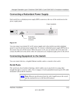
Managed Stackable Layer 3 Switches GSM7328S v2 and GSM7352S v2 Hardware Installation For information about working with the CLI, see the Command Line Interface Reference for the ProSafe 7300S Series Layer-3 Stackable Switches on the Resource CD that shipped with your product. Power Module Bay The power module bay provides an easy way to replace a failed power module (APS135W). If the switch needs to continue to operate while you replace the power supply, an appropriate Redundant Power Supply (RPS) must be used to connect to the redundant power supply connector on the switch rear panel. Installing a Power Module (APS135W) To install a power module, follow these steps: Warning: When inserting a power module into the switch, do not use unnessary force. Doing so can damage the connectors on the rear of the supply and on the midplane. 1. Insert the new power supply module into the power module slot, and gently push the module into the slot. 2. Align the two captive screws with the screw holes in the switch's rear panel. 3. Using a screw driver, gently tighten the captive screws. 4. Connect the power cord to the module and to an AC-powered outlet. Removing a Power Module (APS135W) To remove a power module, follow these steps: 1. Disconnect the power cord from the power module. 2. Remove the power cord from the power connector. 3. Loosen the two captive screws on the power module. 4. Remove the power module from the power module slot by pulling on the extraction handle. 3-10 v1.0, July 2009 Hardware Installation
-
 1
1 -
2
-
3
-
4
-
5
-
6
-
7
-
8
-
9
-
10
-
11
-
12
-
13
-
14
-
15
-
16
-
17
-
18
-
19
-
20
-
21
-
22
-
23
-
24
-
 25
25 -
 26
26 -
 27
27 -
 28
28 -
 29
29 -
 30
30 -
 31
31 -
 32
32 -
 33
33 -
 34
34 -
 35
35 -
36
-
37
-
38
-
39
-
40
-
41
-
42
 |
 |
