Netgear M4300-52G Hardware Installation Guide - Page 58
Optional Step 6: Install a power supply unit
 |
View all Netgear M4300-52G manuals
Add to My Manuals
Save this manual to your list of manuals |
Page 58 highlights
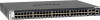
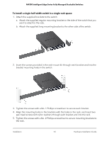
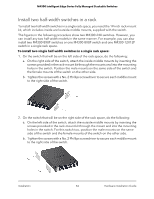
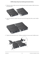
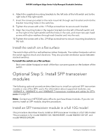
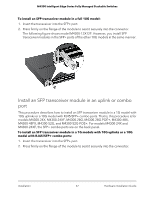
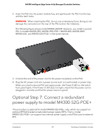
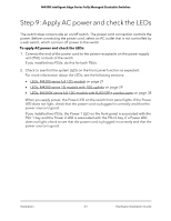
M4300 Intelligent Edge Series Fully Managed Stackable Switches The following figure shows model M4300-48X. However, you install SFP transceiver modules in the SFP+ ports of the 1G models with 10G uplinks or the 10G models with RJ45/SFP+ combo ports in the same manner. Optional Step 6: Install a power supply unit The supported power supply unit (PSU) or PSUs depend on the switch model. For more information, see Power supply units on page 44. The PSU for model M4300-16X might be in the product package, in which case you must install it in the power module bay. The following full-width models provide a second power module bay in which you can install an optional second PSU: • M4300-24X24F, M4300-48X, and M4300-48XF • M4300-28G and M4300-28G-POE+ • M4300-52G and M4300-52G-POE+ For these models, the PSU that is shipped with the product is installed in the power supply bay on the left, which is marked PSU1. You can install the second PSU in the power supply bay on the right, which is marked PSU2. The switch can continue to operate while you install a second PSU. To install a PSU: 1. Pull out the cover plate from the power module bay. For models with two power modules bays, the PSU that is shipped with the product is installed in the left power supply bay. The second power supply bay is the one on the right. Installation 58 Hardware Installation Guide
-
 1
1 -
2
-
3
-
4
-
5
-
6
-
7
-
8
-
9
-
10
-
11
-
12
-
13
-
14
-
15
-
16
-
17
-
18
-
19
-
20
-
21
-
22
-
23
-
24
-
25
-
26
-
27
-
28
-
29
-
30
-
31
-
32
-
33
-
34
-
35
-
36
-
37
-
38
-
39
-
40
-
41
-
42
-
43
-
44
-
45
-
46
-
47
-
48
-
49
-
50
-
51
-
52
-
 53
53 -
 54
54 -
 55
55 -
 56
56 -
 57
57 -
 58
58 -
 59
59 -
 60
60 -
 61
61 -
 62
62 -
 63
63 -
64
-
65
-
66
-
67
-
68
-
69
 |
 |
