Netgear M4300-96X Installation Guide - Page 1
Netgear M4300-96X Manual
 |
View all Netgear M4300-96X manuals
Add to My Manuals
Save this manual to your list of manuals |
Page 1 highlights
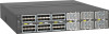
Installation Guide NETGEAR Fully Managed Switches Model M4300-96X Set Up the Switch Prepare the installation site so that mounting, access, power source, and environmental requirements are met. For more information about these requirements, see the hardware installation guide on the resource CD. To set up the switch: 1. Install the switch in a rack. Use the rack-mount kit that is supplied with your switch, following the installation instructions in the hardware installation guide. 2. If required, install a power supply unit (PSU). Then, apply AC power. You can install either an APS600W or, for additional PoE and PoE+ connections, an APS1200W PSU. The Power LED lights solid yellow while the switch conducts a power-on self-test (POST). After the switch passes the POST, the Power LED lights solid green, and the switch is functional. If the Power LED does not light at all or remains solid yellow, see the troubleshooting section of the hardware installation guide for more information. Note: For information about installing a PSU, see the power supply installation guide and the hardware installation guide. 3. If required, install modules in the switch. The switch supports the following port cards: • APM408C. Provides eight 100M/1G/2.5G/5G/10GBASE-T ports. For a copper port at 10 Gbps, use a Category 6 or better (Cat 6, Cat 6a, or Cat 7) cable. • APM408P. Provides eight 100M/1G/2.5G/5G/10GBASE-T PoE+ ports. Slots 1-6 of the switch support PoE and PoE+. • APM408F. Provides eight 1G/10GBASE-X SFP+ ports in which you can install 1G and 10G transceiver modules (GBICs) or direct-attach cables (DACs). For a fiber port, use either a transceiver module (GBIC) or an AXC761 (1 m), AXC763 (3 m), AXC765 (5 m), AXC767 (7 m), AXC7610 (10 m), AXC7615 (15 m), or AXC7620 (20 m) direct-attach cable (DAC). • APM402XL. Provides two 40GBASE-X QSFP+ ports in which you can install QSFP+ modules, break-out cables, or DACs. For an APM402XL port connection at 40 Gbps, use modules or cables that are compatible with 40GBASE-SR4, 40GBASE-LR4, and 40GBASE-CR4. 4. Connect devices to the switch. Note: For information about installing port cards, see the switch port card installation guide and the hardware installation guide. The hardware installation guide also provides information about the supported transceiver modules (GBICs) that you can install in the APM408F port card. You can download the installation guides by visiting netgear.com/support/product/M4300-96X.aspx#docs. Perform the Initial Configuration You can access the switch through the out-of-band (OOB) port (which is also referred to as the service port), through a console port, or through any Ethernet network port. By default, the switch functions as a DHCP client. To configure the IP address of the switch, use one of the following methods: • Local browser-based management interface. Use the local browser-based management interface through the OOB port or any Ethernet network port (see Use the Local Browser Interface for Initial Configuration). • CLI. Use the CLI through the mini USB console port or RJ-45 RS232 console port. You can configure the IP address manually or use the ezconfig utility (see Use the CLI for Initial Configuration). • DHCP server. Connect a DHCP server through the OOB port or through any Ethernet network port and find the assigned IP address (see Find the IP Address Assigned by a DHCP Server). After you configure or find the IP address of the switch, you can configure the features of the switch through the local browser interface or the CLI. Use the Local Browser Interface for Initial Configuration You can use a computer that functions in the same subnet as the switch to access the local browser interface over the switch's default IP address and assign another static IP address to the switch. To access the local browser interface over the switch's default IP address: 1. Configure your computer with a static IP address: • For access over an Ethernet network port, use an IP address in the 169.254.0.0/16 subnet. For example, use 169.254.100.201. • For access over the OOB port, use an IP address in the 192.168.0.0/16 subnet. For example, use 192.168.0.100. 2. Connect an Ethernet cable from an Ethernet port on your computer to an Ethernet network port on the switch or to the OOB port on the switch. 3. Launch a web browser such as Google Chrome, Mozilla Firefox, or Microsoft Internet Explorer. 4. Enter the default IP address of the switch in the web browser address field: • For access over an Ethernet network port, enter 169.254.100.100. • For access over the OOB port, enter 192.168.0.239. A login window displays. 5. Enter admin for the user name, leave the password field blank, and click the LOGIN button. The System Information page displays. 6. To configure the IP address of the switch, management interface, and OOB port, select System > Management, and select an option from the menu on the left.
-
 1
1 -
 2
2
 |
 |
