Netgear WFS709TP WFS709TP Hardware manual - Page 14
Front and Rear View, System Indicator LEDs - setup
 |
UPC - 606449052336
View all Netgear WFS709TP manuals
Add to My Manuals
Save this manual to your list of manuals |
Page 14 highlights
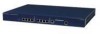
WFS709TP ProSafe Smart Wireless Switch Hardware Installation Guide • 1U chassis can be mounted in a standard 19-inch network equipment rack. • The firmware can be easily upgraded as future software releases are made available. You can install upgrades using HTTP. Front and Rear View The standard version of the WFS709TP ProSafe Smart Wireless Switch contains a 1000BASE-T copper Gigabit Ethernet (GE) connector. Figure 1-1 shows the front and rear views of the switch. Figure 1-1 System Indicator LEDs 1 The system LEDs, located on the front of the switch, display the status of system power and operation. Table 1-1. System LEDs LED Power Status State Green Off Green Off Description WFS709TP is receiving proper power. WFS709TP is powered off. WFS709TP has booted and is functioning properly. WFS709TP is booting, loading software, or has failed. Note: This LED remains off until you perform the initial setup described in the document Installation Guide: WFS709TP ProSafe Smart Wireless Switch. 1-2 Introduction v1.0, May 2007
-
 1
1 -
2
-
3
-
4
-
5
-
6
-
7
-
8
-
 9
9 -
 10
10 -
 11
11 -
 12
12 -
 13
13 -
 14
14 -
 15
15 -
 16
16 -
 17
17 -
 18
18 -
 19
19 -
20
-
21
-
22
-
23
-
24
-
25
-
26
-
27
-
28
-
29
-
30
-
31
-
32
-
33
-
34
-
35
-
36
 |
 |
