Nokia IP290 Installation Guide - Page 18
System Status LEDs, Nokia IP290 Security Platform Installation Guide, Appliance Status LEDs
 |
View all Nokia IP290 manuals
Add to My Manuals
Save this manual to your list of manuals |
Page 18 highlights
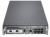
1 Overview Note The only modem approved for use with Nokia security appliances with USB AUX ports is the Radicom model V92MB-U-E, and you must be using Nokia IPSO 6.1 or greater. System Status LEDs You can monitor the basic operation of Nokia IP290 appliances by checking their status LEDs. The system status LEDs are located on the front panel of the appliance, as Figure 4 shows. Figure 4 Appliance Status LEDs Power or Status Caution Critical STATUS POWER FAULT IP290 1 3 5 1000BaseT LINK ACT SLOT 1 LINK ACT RESET AUX CONSOLE 2 4 6 00557 Figure 3 describes the status conditions for each of the LEDs for all indications they might display. Table 3 Appliance Status LEDs Indicator Color Description Caution None (off) Normal Yellow (steady) Yellow (blinking) Initial boot flash activity or Internal voltage problem Temperature fault 18 Nokia IP290 Security Platform Installation Guide
-
 1
1 -
2
-
3
-
4
-
5
-
6
-
7
-
8
-
9
-
10
-
11
-
12
-
 13
13 -
 14
14 -
 15
15 -
 16
16 -
 17
17 -
 18
18 -
 19
19 -
 20
20 -
 21
21 -
 22
22 -
 23
23 -
24
-
25
-
26
-
27
-
28
-
29
-
30
-
31
-
32
-
33
-
34
-
35
-
36
-
37
-
38
-
39
-
40
-
41
-
42
-
43
-
44
-
45
-
46
-
47
-
48
-
49
-
50
-
51
-
52
-
53
-
54
-
55
-
56
-
57
-
58
-
59
-
60
-
61
-
62
-
63
-
64
-
65
-
66
-
67
-
68
-
69
-
70
-
71
-
72
-
73
-
74
-
75
-
76
-
77
-
78
-
79
-
80
-
81
 |
 |
