NordicTrack 5500 R Treadmill English Manual - Page 8
Optional Chest Pulse Assembly
 |
View all NordicTrack 5500 R Treadmill manuals
Add to My Manuals
Save this manual to your list of manuals |
Page 8 highlights
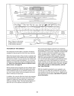
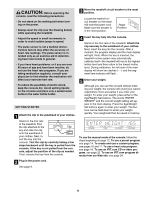
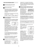
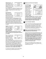
OPTIONAL CHEST PULSE ASSEMBLY If you purchase the optional chest pulse sensor (see page 25), follow the steps below to install the receiver and the short jumper wire included with the chest pulse sensor. 1. While holding the Upper Handrail (19), remove the two 3" Bolts (56) and Handrail Washers (69) from the 1 19 Uprights (99) as shown. 118 118 99 69 56 56 2. Make sure that the power cord is unplugged. Remove the indicated screws from the Console Back (89). 2 81 Important: The screws may be different lengths. Remember which screws were removed from which holes. Remove the Console (81). 89 Screws 3. Peel the paper off the pad on the bottom of the receiver (A). Turn the receiver so the small cylinder is on the 3 side shown, and press the receiver into the bottom of the Console Base (130) in the indicated location. 4. Connect the included short jumper wire (B) to the wire on the receiver (A). Connect the other end of the short 4 jumper wire to the PLS2 jack on the back of the Console (81). If there is a wire already plugged into the PLS2 jack, unplug it. Note: The other wires included with the receiver may be discarded. Use the included wire tie to secure wires, if needed. Make sure that no wires are pinched. See step 2. Reattach the Console (81) with the screws. Important: If the screws are not put back into the same holes from which they were removed, the Console will be damaged. See step 1. Reattach the Upper Handrail (19). A Cylinder 130 81 PLS2 Jack B A 8
-
 1
1 -
2
-
 3
3 -
 4
4 -
 5
5 -
 6
6 -
 7
7 -
 8
8 -
 9
9 -
 10
10 -
 11
11 -
 12
12 -
 13
13 -
14
-
15
-
16
-
17
-
18
-
19
-
20
-
21
-
22
-
23
-
24
-
25
-
26
-
27
-
28
-
29
-
30
-
31
-
32
-
33
-
34
-
35
-
36
-
37
-
38
 |
 |
