NordicTrack Apex 6100xi English Manual - Page 7
Set the Handrails 73 on the Handrail Spacers 92
 |
View all NordicTrack Apex 6100xi manuals
Add to My Manuals
Save this manual to your list of manuals |
Page 7 highlights
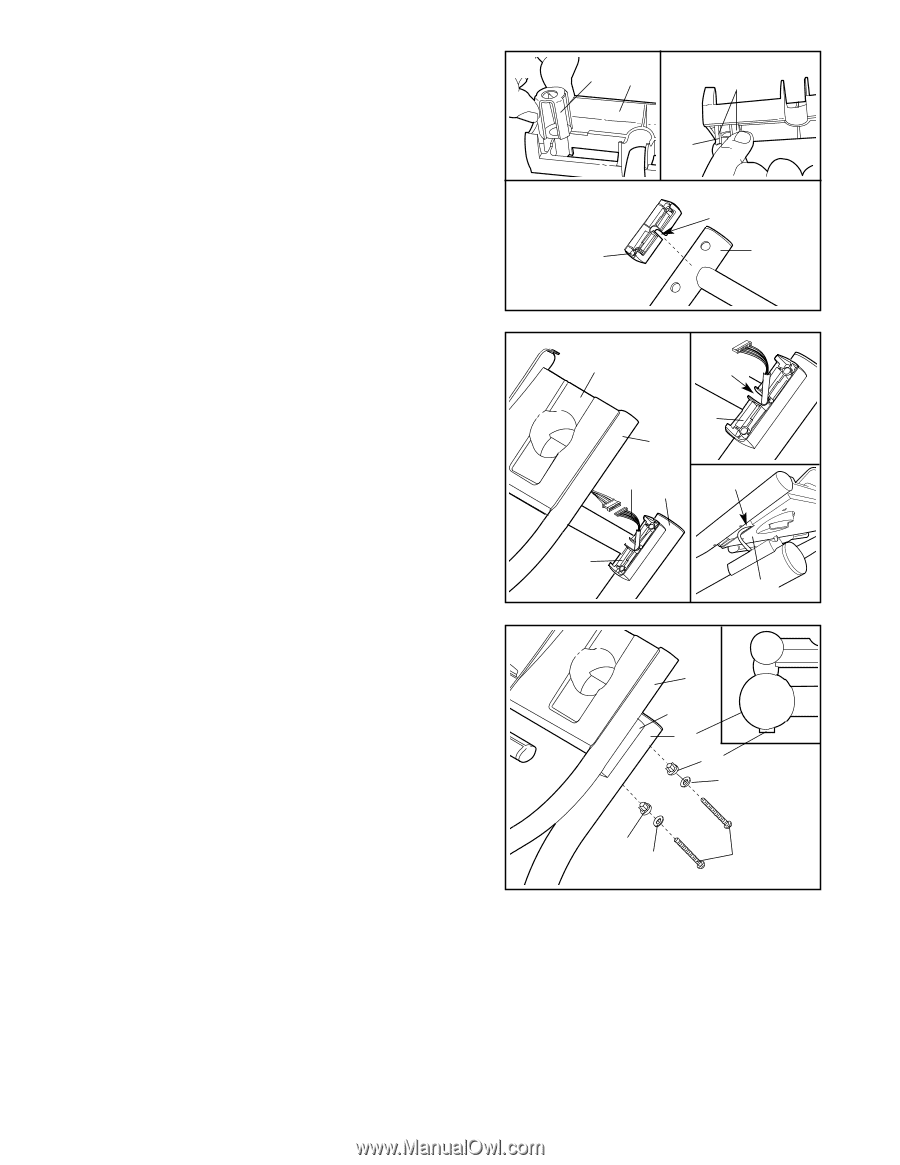
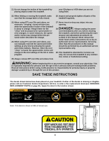
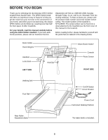
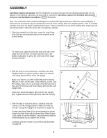
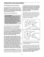
4. Slide the Grounding Bracket (71) onto one of the Handrail Spacers (92) in the location shown. 4 See inset drawing A. Pinch the tabs on the Grounding Bracket (71) so that the tabs will fit into the hole in the left Upright (83 [see inset drawing B]). See inset drawing B. Place the Handrail Spacer (92) on B the left Upright (83) as shown, with the cutout on the indi- cated side. Note: Make sure that the tabs on the Grounding Bracket (71 [see inset drawing A]) are inserted into the hole in the left Upright. A 71 92 Tabs 71 Cutout 92 83 5. Place the other Handrail Spacer (92) on the right Upright 5 (83) as shown, with the cutout on the indicated side (see inset drawing A). Pull the Upright Wire Harness (131) up through the cutout. Have a second person hold the Handrails (73) near the Uprights (83) as shown. Connect the Upright Wire Harness (131) to the wires extending from the right Handrail. Insert the connectors and the Upright Wire Harness (131) into the opening in the Console Base (79 [see inset drawing B]). Set the Handrails (73) on the Handrail Spacers (92), being careful not to pinch the Wire Harness (131). 6. Insert two Handrail Bolts (96) with Handrail Washers (95) and Handrail Bushings (94) into the right Upright 6 (83) and the right Handrail Spacer (92). Turn the Handrail Bushings (94) so that they fit against the Upright as shown in the inset drawing. Lift up the right Handrail (73) and align the Bolts with the holes in the Handrail. Next, thread the Bolts into the Handrail. Do not tighten the Bolts yet. Attach the left Handrail (not shown) in the same way. Tighten all four Handrail Bolts (96). A 79 Cutout 92 73 131 83 B 131 92 79 73 92 83 94 95 94 95 96 7. Make sure that all parts are properly tightened before you use the treadmill. Keep the included allen wrench in a secure place. The allen wrench is used to adjust the walking belt (see page 27). To protect the floor or carpet from damage, place a mat under the treadmill. 7
-
 1
1 -
 2
2 -
 3
3 -
 4
4 -
 5
5 -
 6
6 -
 7
7 -
 8
8 -
 9
9 -
 10
10 -
 11
11 -
 12
12 -
13
-
14
-
15
-
16
-
17
-
18
-
19
-
20
-
21
-
22
-
23
-
24
-
25
-
26
-
27
-
28
-
29
-
30
-
31
-
32
-
33
-
34
 |
 |