NordicTrack C 2300 Treadmill English Manual - Page 7
Note: A replacement Base Pad 99 may be included. Use - treadmill
 |
View all NordicTrack C 2300 Treadmill manuals
Add to My Manuals
Save this manual to your list of manuals |
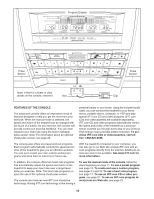
Page 7 highlights
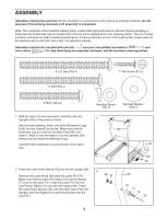
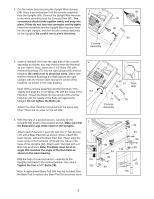
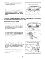
3. Cut the rubber band securing the Upright Wire Harness (98). Have a second person hold the console assembly 3 near the Uprights (69). Connect the Upright Wire Harness to the wires extending from the Console Base (81). The connectors should slide together easily and snap into place. If they do not, turn one connector and try again. Insert the connectors and the Upright Wire Harness down into the right Upright, and then set the console assembly on the Uprights. Be careful not to pinch the wires. Console Assembly 98 81 98 69 4. Insert a Handrail (118) into the right side of the console 4 assembly as shown; you may need to twist the Handrail as you insert it. Next, insert two 4 1/2" Bolts (78) with Handrail Bushings (77) into the right Upright (69) and the Handrail. Be careful not to pinch the wires. Make sure that the Handrail Bushings are flush against the right Upright, with the thicker sides facing the center of the treadmill, as shown in the inset drawing. Next, lift the console assembly and the Handrail (118) slightly and align the 4 1/2" Bolts (78) with the holes in the 118 Handrail. Thread the Bolts into the Upright (69) and the Handrail until the heads of the Bolts are against the Upright. Do not tighten the Bolts yet. Attach the other Handrail (not shown) in the same way. Note: There are no wires on the left side. 5. With the help of a second person, carefully tip the Uprights (69) down to the position shown. Make sure that the Extension Legs (102) remain in the Uprights. Attach each Extension Leg (102) with two 1" Tek Screws (47) and a Base Pad (99) as shown. (Note: Attach the lower Screw, without the Base Pad, first.) Next, align the lower ends of the Handrails (118) with the holes in the base of the Uprights (69). Attach each Handrail with a 4" Bolt (53) as shown. Note: The Bolts must be at an angle that matches the angle of the Handrails as shown in the inset drawing. With the help of a second person, carefully tip the Uprights (69) back to the vertical position. See step 4. Tighten the four 4 1/2" Bolts (78). Note: A replacement Base Pad (99) may be included. Use the Base Pad to replace any Base Pad that becomes worn. 5 69 118 102 69 77 Thick Side 77 78 Console Assembly 99 53 99 47 99 99 102 53 99 47 99 53 118 7
-
 1
1 -
 2
2 -
 3
3 -
 4
4 -
 5
5 -
 6
6 -
 7
7 -
 8
8 -
 9
9 -
 10
10 -
 11
11 -
 12
12 -
13
-
14
-
15
-
16
-
17
-
18
-
19
-
20
-
21
-
22
-
23
-
24
-
25
-
26
-
27
-
28
-
29
-
30
-
31
-
32
-
33
-
34
 |
 |
