NordicTrack C2150 Treadmill English Manual - Page 7
The Console May Be Damaged When - treadmills
 |
View all NordicTrack C2150 Treadmill manuals
Add to My Manuals
Save this manual to your list of manuals |
Page 7 highlights
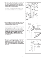
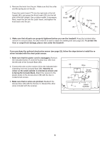
2. Attach the four Base Pads (81) to the base of the Uprights (85) in the indicated locations with four 1" Tek Screws 2 (82) and four Plastic Spacers (101). Note: One replace- ment Base Pad may be included. Use the Base Pad to re- place any Base Pad that becomes worn. With the help of a second person, carefully tip the tread- mill down so the four Base Pads (81) are resting on the 101 floor and the Uprights (85) are in the vertical position. 55 101 101 81 82 85 101 81 82 3. Remove the band securing the Upright Wire Harness (73) 3 to the right Upright (85). Have a second person hold the Console console assembly near the right Upright. Assembly Connect the Upright Wire Harness (73) to the wires extend- ing from the console assembly. Make sure to connect the connectors properly (see the inset drawing). The con- nectors should slide together easily and snap into place. If the connectors do not slide together easily and snap into place, turn one connector and try again. IF THE 85 CONNECTORS ARE NOT CONNECTED PROPERLY, THE CONSOLE MAY BE DAMAGED WHEN THE POWER IS TURNED ON. Insert the connectors into the right Upright (85). 73 73 4. With the help of a second person, set the console assem- 4 bly on the Uprights (85). Make sure that no wires are pinched. Attach the console assembly with four Console Bolts (72) and four Star Washers (67) (only one side is shown). Start all four Console Bolts before tightening 85 any of them. 67 72 Console Assembly 67 7
-
 1
1 -
 2
2 -
 3
3 -
 4
4 -
 5
5 -
 6
6 -
 7
7 -
 8
8 -
 9
9 -
 10
10 -
 11
11 -
 12
12 -
13
-
14
-
15
-
16
-
17
-
18
-
19
-
20
-
21
-
22
-
23
-
24
-
25
-
26
-
27
-
28
-
29
-
30
-
31
-
32
-
33
-
34
 |
 |
