NordicTrack Elite 5.4 Bike English Manual - Page 10
Tip: Avoid pinching the Right Pulse Wire
 |
View all NordicTrack Elite 5.4 Bike manuals
Add to My Manuals
Save this manual to your list of manuals |
Page 10 highlights
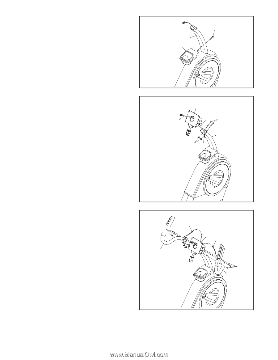
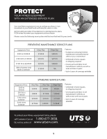
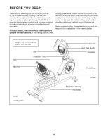
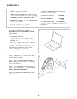
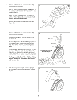
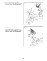
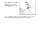
6. Attach the Accessory Tray (9) to the Upright (4) with an M6 x 50mm Screw (42). 6 42 4 9 7. Untie and discard the wire tie on the Main Wire (41). While a second person holds the Console Bracket (82) assembly near the Upright (4), route the Main Wire (41) through the notch in the Upright, through the Upright Bracket (84), and through the hole in the center of the Console Bracket. Tip: Avoid pinching the Main Wire (41). Insert the Upright Bracket (84) into the Upright (4). Attach the Upright Bracket (84) with two M8 x 50mm Bolts (49) and two M8 Locknuts (102); start both Bolts, and then tighten them. Make sure that the Locknuts are in the hexagonal holes (A). 7 82 41 84 49 4 102 A Avoid pinching the Main Wire (41) 8. Identify the Right Handlebar (81) and orient it as shown. Tip: Avoid pinching the Right Pulse Wire (8). Attach the Right Handlebar (81) to the right side of the Console Bracket (82) with three M8 x 13mm Screws (94); start all the Screws, and then tighten them. Then, route the Right Pulse Wire (8) in the Right Handlebar (81) through the Console Bracket (82) as shown. Repeat this step to attach the Left Handlebar (6). 8 94 7 6 Avoid pinching the wires 82 8 94 81 10
-
 1
1 -
2
-
3
-
4
-
 5
5 -
 6
6 -
 7
7 -
 8
8 -
 9
9 -
 10
10 -
 11
11 -
 12
12 -
 13
13 -
 14
14 -
 15
15 -
16
-
17
-
18
-
19
-
20
-
21
-
22
-
23
-
24
-
25
-
26
-
27
-
28
-
29
-
30
-
31
-
32
 |
 |