NordicTrack Ex3600 Treadmill User Manual - Page 9
Be Damaged When The Power Is Turned On.
 |
View all NordicTrack Ex3600 Treadmill manuals
Add to My Manuals
Save this manual to your list of manuals |
Page 9 highlights
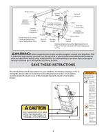
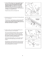
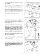
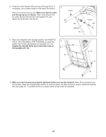
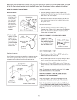
5. Remove the Spring Pin (102) from the lower end of the Gas Spring (88). Next, press the lower end of the Gas Spring (88) onto the ball on the bracket on the Base (83). If necessary, pivot the Frame (48) slightly and rotate the Gas Spring to align the end of the Gas Spring with the ball on the bracket. See drawing 5a. Insert the end of the Spring Pin (102) into two of the small holes in the end of the Gas Spring (88). Then, rotate the Spring Pin until it clips onto the Gas Spring. Carefully lower the Frame (48) to the floor. 5 83 102 5a 48 88 Bracket 88 102 Bracket 6. Remove the elastic bands securing the Upright Wire (75) and the TV Cable (110). Next, insert the Upright Wire and the TV Cable through the Handrail Spacers (95) as shown, and press the Handrail Spacers into the tops of the Uprights (73, 74). With the help of a second person, hold the console assembly near the Uprights (73, 74). Connect the Upright Wire (75) to the wire harness on the console assembly. Make sure to connect the connectors properly (see the inset drawing); the connectors should slide together easily and snap into place. If the connectors do not slide together easily and snap into place, turn one connector and try again. IF THE CONNECTORS ARE NOT CONNECTED PROPERLY, THE CONSOLE MAY BE DAMAGED WHEN THE POWER IS TURNED ON. Next, connect the TV Cable (110) to the cable on the left side of the console assembly. Insert the Upright Wire (75) and the TV Cable (110) down into the Uprights (73, 74). Next, insert the brackets on the console assembly into the Uprights. Be careful not to pinch the wires. 6 Cable 110 Console 95 Assembly 73 95 Console Wire 75 74 75 7. Finger tighten three Handrail Bolts (64), with three Handrail Star Washers (90), into the Right Upright (74) and console assembly. Repeat with the Left Upright (73). After all six Handrail Bolts have been started, tighten the four front Handrail Bolts before tightening the other two Bolts. 7 Console Assembly 73 64 90 64 90 74 9
-
 1
1 -
2
-
3
-
 4
4 -
 5
5 -
 6
6 -
 7
7 -
 8
8 -
 9
9 -
 10
10 -
 11
11 -
 12
12 -
 13
13 -
 14
14 -
15
-
16
-
17
-
18
-
19
-
20
-
21
-
22
-
23
-
24
-
25
-
26
-
27
-
28
-
29
-
30
-
31
-
32
-
33
-
34
-
35
-
36
-
37
-
38
 |
 |
