Oki B6500 Guide: Setup, B6500 (E/F/S/P) - Page 4
Locating parts of the printer, Preparing a location for the, printer - duplex
 |
View all Oki B6500 manuals
Add to My Manuals
Save this manual to your list of manuals |
Page 4 highlights
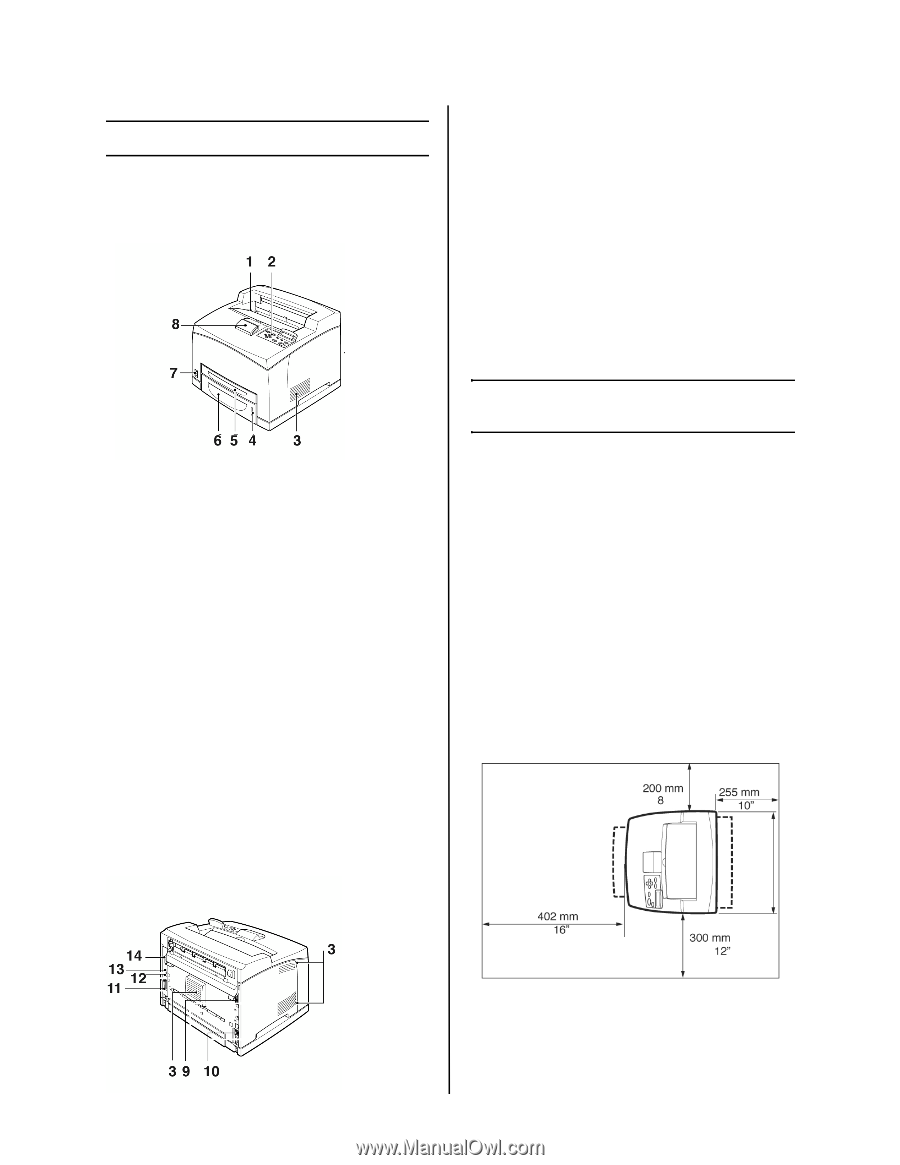
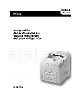
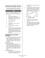
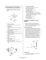
Locating parts of the printer The main parts of the printer and a brief description of their functions are shown below: 1 Center output tray Print jobs are output here with printed side facing down. 2 Control panel Consists of the control buttons, indicators and display. For control panel details, refer to "The Control Panel and Menu system" on page 8. 3 Ventilation slots Provide ventilation for the interior of the printer. 4 Paper level indicator Indicates the level of the remaining paper in the 550-sheet paper tray. 5 Tray 1 Holds 150 sheets of paper. 6 Tray 2 Holds 550 sheets of paper. 7 Power switch Switches the printer power on and off. 8 Extension output tray Pull this tray out to print on paper larger than Letter. 9 Duplex unit connector For connecting the duplex unit (option). 10 Power cord connector For connecting the power cord. 11 Parallel connector For connecting a parallel cable. 12 Network connector For connecting the network cable when using the printer as a network printer. (The Network Software Kit option needs to have been installed to enable networking capability.) 13 USB connector For connecting a USB cable. 14 Serial connector For connecting a serial cable. Preparing a location for the printer Place the machine on a level and sturdy surface that can withstand the machine weight, 22.6 kg (50lb). If tilted, the machine may fall over and cause injuries. Space requirements The printer has ventilation holes on the side and rear panels. Ensure that the printer is installed with a minimum clearance of 255mm (10in) from the rear vent to any wall, 200mm (8in) from the left vent to any wall, and 300mm (12in) from the right vent to any wall. A poorly ventilated machine can cause excessive internal heat and fire. The following diagram shows the minimum clearances required for normal operation, consumables replacement, and maintenance to ensure your machine operates at peak performance. Environment Ensure that the installation location meets the following conditions: B6500 Series Setup Guide English - 4
-
 1
1 -
 2
2 -
 3
3 -
 4
4 -
 5
5 -
 6
6 -
 7
7 -
 8
8 -
 9
9 -
 10
10 -
11
-
12
-
13
-
14
-
15
-
16
-
17
-
18
-
19
-
20
-
21
-
22
-
23
-
24
-
25
-
26
-
27
-
28
-
29
-
30
-
31
-
32
-
33
-
34
-
35
-
36
-
37
-
38
-
39
-
40
-
41
-
42
-
43
-
44
 |
 |