Optoma DW326e User Manual - Page 8
Input/Output Connections, HDMI Connector, SCART, S-Video Input Connector
 |
View all Optoma DW326e manuals
Add to My Manuals
Save this manual to your list of manuals |
Page 8 highlights
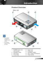
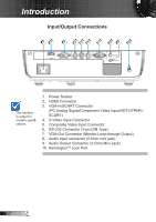
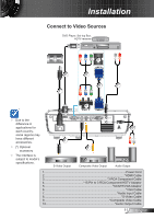
Introduction Input/Output Connections 12 3 45 6 7 89 10 HDMI VGA- IN / SCART S-VIDEO VIDEO RS232 VGA-OUT AUDIO-IN AUDIO-OUT The interface is subject to model's specifications. 1. Power Socket 2. HDMI Connector 3. VGA-In/SCART Connector (PC Analog Signal/Component Video Input/HDTV/YPbPr/ SCART) 4. S-Video Input Connector 5. Composite Video Input Connector 6. RS-232 Connector (3-pin DIN Type) 7. VGA-Out Connector (Monitor Loop-through Output) 8. Audio Input connector (3.5mm mini jack) 9. Audio Output Connector (3.5mm Mini Jack) 10. KensingtonTM Lock Port English 8
-
 1
1 -
2
-
 3
3 -
 4
4 -
 5
5 -
 6
6 -
 7
7 -
 8
8 -
 9
9 -
 10
10 -
 11
11 -
 12
12 -
 13
13 -
14
-
15
-
16
-
17
-
18
-
19
-
20
-
21
-
22
-
23
-
24
-
25
-
26
-
27
-
28
-
29
-
30
-
31
-
32
-
33
-
34
-
35
-
36
-
37
-
38
-
39
-
40
-
41
-
42
-
43
-
44
-
45
-
46
-
47
-
48
-
49
-
50
-
51
-
52
-
53
-
54
-
55
-
56
-
57
-
58
-
59
 |
 |

8
English
Introduction
Input/Output Connections
Power Socket
1.
HDMI Connector
2.
VGA-In/SCART Connector
3.
(PC Analog Signal/Component Video Input/HDTV/YPbPr/
SCART)
S-Video Input Connector
4.
Composite Video Input Connector
5.
RS-232 Connector (3-pin DIN Type)
6.
VGA-Out Connector (Monitor Loop-through Output)
7.
Audio Input connector (3.5mm mini jack)
8.
Audio Output Connector (3.5mm Mini Jack)
9.
Kensington
10.
TM
Lock Port
VGA- IN / SCART
S-VIDEO
VIDEO
RS232
AUDIO-IN
AUDIO-OUT
VGA-OUT
HDMI
2
1
9
3
4
5
6
7
8
10
The interface
is subject to
model’s specifi
-
cations.