Panamax M4315-PRO Quick Start Guide - Page 3
Panamax Limited Product Warranty, 5,000,000 Connected Equipment Limited Protection Policy - furman
 |
View all Panamax M4315-PRO manuals
Add to My Manuals
Save this manual to your list of manuals |
Page 3 highlights
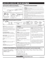
REAR PANEL FEATURE OVERVIEW OUTLET 8 OUTLET 7 AC INLET OUTLET 8 OUTLET 7 OUTLET 6 OUTLET 5 FILTER BANK 4 M4320-PRO GROUND FILTER BANK 4 - HIGH CURRENT FILTER BANK 3 3-B 1. 2. 3-A 3. 1. Power inlet: M4315-PRO (120 Vac/15 A, IEC 320 C14) do not remove steel retention clip. M4320-PRO (120 Vac/20 A, IEC 320 C20) do not remove steel retention clip. OUTLET 4 OUTLET 3 OUTLET 2 OUTLET 1 BlueBOLT-CV1 9. FILTER BANK 2 FILTER BANK 1 CATV / SAT 1 CATV / SAT 2 LAN CAT 5e 8. DC TRIGGER O U IN T TELCO 3-A 3-A 4. 5. 6. 7. 4. CATV/SAT 1 & 2: Universal voltage (±75V clamping), HD 1080i/p ready,
-
 1
1 -
 2
2 -
 3
3 -
 4
4 -
 5
5 -
 6
6 -
 7
7 -
 8
8
 |
 |

1.
Power inlet:
M4315-PRO (120 Vac/15 A, IEC 320 C14) do not remove steel retention
clip.
M4320-PRO (120 Vac/20 A, IEC 320 C20) do not remove steel retention clip.
2. Ground lug:
connect to Panamax MOD-series signal protection module grounding busses
with 14 AWG (<12” length) wire to expand signal protection capabilities
3. Outlets:
all rear panel outlets are separately controlled. They are grouped into four (4)
filter-isolated banks.
3-A
BANKS 1-3: filtered outlet s (>76 dB @ 5 KHz – 150 KHz,
>46 dB @ 150 KHz – 5 MHz)
3-B
BANK 4: high-current outlets (>59 dB, 5 KHz – 450 KHz,
>46 dB @ 450 KHz – 5 MHz)
4. CATV/SAT 1 & 2:
Universal voltage (±75V clamping), HD 1080i/p ready, <0.5 dB @
0 Hz - 2.2 GHz.
5. LAN Cat 5e
(10/100/1000BASE-T compatible): RJ-45 (8P8C) Ethernet protection
pass-through.
6. Telco:
RJ-11 (6P2C) analog telephone/DSL protection pass-through.
Do not connect in reverse (IN comes in from wall, OUT connects to equipment).
7. DC Trigger Input:
3.5mm mono jack, ± (5-24 VDC) tip-ring.
8. TCP/IP card (BlueBOLT)
installed
9. Communications card:
RS-232 (female DE-9)
included, not installed.
GROUND
OUTLET 8
OUTLET 7
OUTLET 6
OUTLET 5
OUTLET 4
OUTLET 3
OUTLET 2
OUTLET 1
FILTER BANK 3
FILTER BANK 2
FILTER BANK 1
CATV / SAT 1
CATV / SAT 2
LAN CAT 5e
TELCO
DC
TRIGGER
AC INLET
FILTER BANK 4 - HIGH CURRENT
IN
O
U
T
1.
2.
3.
4.
5.
6.
8.
OUTLET 8
OUTLET 7
FILTER BANK 4
3-A
3-A
3-A
3-B
7.
BlueBOLT-CV1
M4320-PRO
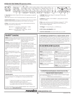
BlueBOLT™ (Installed)
RS-232 INSTALLATION (optional)
It is recommended that you read the entire instructions list before proceeding.
The BlueBOLTCV-1 should already be factory installed in this Panamax Pro component.
To switch from BlueBOLT functionality to RS-232 connectivity, follow these steps:
CAUTION! WARRANTY LIMITATION FOR INTERNET PURCHASERS
Panamax products purchased through the Internet do not carry a valid Product Warranty or
Connected Equipment Protection Policy unless purchased from an Authorized Panamax Internet
Dealer and the original factory serial numbers are intact (they must not have been removed, defaced
or replaced in any way). Purchasing from an Authorized Panamax Internet Dealer insures that the
product was intended for consumer use, has passed all quality inspections and is safe. Buying
through auction sites or unauthorized dealers may result in the purchase of salvaged, failed and/or
products not intended for use in the US. In addition, Authorized Panamax Internet dealers have
demonstrated sufficient expertise to insure warranty compliant installations.
For a list of Authorized Panamax Internet Dealers go to www.panamax.com
Panamax Limited Product Warranty*
Panamax Inc. warrants to the purchaser of this product for a period of three (3) years from the date of
purchase, that
the unit shall be free of defects in design, material or workmanship, and Panamax Inc. will
repair or replace any defective unit.
QSG00859 REV. G
ENG
2.
REAR PANEL FEATURE OVERVIEW
*Full Warranty and policy Information available at www.panamax.com
$5,000,000 Connected Equipment Limited Protection Policy*
All Panamax Warranties and Connected Equipment Policies are valid only in the United States & Canada.
This equipment (BlueBOLT™ IP Card) has been tested and found to comply with the limits for a Class B digital device, pursuant
to part 15 of the FCC Rules. These limits are designed to provide reasonable protection against harmful interference in a
residential installation. This equipment generates, uses and can radiate radio frequency energy and, if not installed and used in
accordance with the instructions, may cause harmful interference to radio communications. However, there is no guarantee that
interference will not occur in a particular installation.
FCC CLASS B DIGITAL DEVICE INFORMATION
www.panamax.com
Advanced Operation
Besides providing access to Panamax/Furman’s hosted BlueBOLT platform, the included
BlueBOLT-CV1 card also supports the following networking protocols:
• Telnet (default port 23), for interfacing to control and
automation systems within the local network.
• HTTP (web server at default port 80) for configuring the
network settings for stand-alone “static IP” operation.
For more information, see the application note BlueBOLT Advanced Networking, available
online
at www.mybluebolt.com.
RS232
9.
STEP 1.
Connect an Ethernet cable (sold
separately) between the BlueBOLT-CV1 card
and an Internet router or modem with an
established Internet connection.
STEP 2.
On-Line Registration (Step 2 of 2)
Your BlueBOLT™ enabled Power
Management Component is completely
plug-and-play and does not require any
software installation. The online BlueBOLT™
control interface is operated through your
web browser.
a)
Using any Internet connected computer
go to
www.mybluebolt.com using your
standard Internet browser.
b)
Follow the on screen prompts, add a
location, and then add a device.
Note:
you
will need the BlueBOLT-CV1’s unique MAC
address and challenge key (provided on the
card’s protective packaging as well as on the
label of the card itself) in order to register
the unit online.
c)
Once you input the MAC address and
included challenge key, if BlueBOLT™
cannot detect your device (please allow up
to 20 seconds), please follow the on-
screen troubleshooting guide. Also confirm
the Power Management Component is
properly connected to the Internet.
• Is your Power Management Component
receiving power? Check the power cable
and confirm the unit is on.
• Is your BlueBO
LT-CV1 card installed
properly? The “Link” light should be
illuminated (solid green) and the “Activity”
light should be blinking intermittently
(green).
• Is your Internet connection functioning?
Can you access a general web page?
• Is your BlueBO
LT-CV1 card connected to
your internet router or modem? Check the
Ethernet cable and confirm that the unit is
connected to an active Internet connection,
and make sure those connected devices are
receiving power.
• If you have answered “
Yes” to all of these
questions and are still unable to connect
your Power Management component,
please contact Panamax customer service
at 1-800-472-5555.
STEP
1.
Unplug M4315-PRO or
M4320-PRO Power Management
Component from wall.
STEP
2.
Unplug Ethernet cable from
BlueBOLT-CV1 card.
STEP
3.
Remove the BlueBOLT-CV-1
card using thumbscrews. Note minimal
torque should be applied in removal of
the existing card.
STEP 4.
Remove RS-232 card from
protective packaging.
STEP
5.
Noting the 2 guiding channels
within the card slot, gently slide the
RS-232 card into the card slot, making
sure to screw the thumbscrews down for
a snug and secure fit.
STEP 6
.
Connect RS-232 cable
(sold
separately) to the RS-232 card to
establish to a connection between the
Power Management
component and an
RS-232 enabled Home Theater control
device.
STEP 7
.
Plug in Power Management
Component to an AC power receptacle.