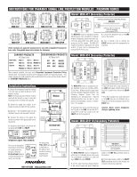
The
MOD-DT4
module is designed to pro-
tect Digital Station (DS) Set phone lines.
Station Set lines that leave the building are a
pathway for surges (backdoor) to enter the
phone system.
This is why the lines
FROM
the Station Sets are connected to the
LINE
side of the module and the
EQUIP
side of
the module is connected to the phone sys-
tem. Multiple input & output jacks provide
complete installation flexibility.
The follow-
ing diagram shows how the jacks/wires are
interconnected.
Different cables/connec-
tions can be split or combined to accommo-
date a variety of installations.
For example:
• Station Set lines from the phone system
can be punched-down on the 110 jack on
the
EQUIP
side and four RJ11 (2 wire)
cords will connect from the LINE side to the
Station Sets.
• Station Set lines from the phone system
can be punched-down on the 110 jack on
the
EQUIP
side and two RJ14 (4 wire) cords
will connect from the LINE side (upper 2
jacks) to the Station Sets.
Caution: Never install telephones
during a lightning storm.
The
MOD-DBSTV
module provides protec-
tion for 3 SAT / CABLE / ANT and 1 tele-
phone line.
1.
Connect the Satellite LNB or Cable TV
coax cable from the wall/floor jack to one of
the “F” connectors labled SAT/CATV on the
module
2.
Use a coax patch cord to connect the
other
SAT/CATV
labeled modular “F” con-
nector to the equipment to be protected.
3.
Repeat steps 1 and 2 for up to 2 addi-
tional satellite or cable TV lines.
4.
Connect the telephone line to the LINE
jack on the module.
5.
Use a modular cord to connect the
EQUIP
modular jack to the equipment to be
protected.
Note:
This reminder is provided to call the
CATV installer’s attention to Article 820-40
of the NEC that provides guidelines for
proper grounding and, in particular, speci-
fies that the cable ground shall be connect-
ed to the grounding system of the building
as close to the point of entry as possible.
The
MOD-SPKP
module is designed to
protect outdoor speaker, keypad, control and
security wires (8 wires or 4 pairs).
Equipment lines that lead outside the build-
ing are pathways for surges (sometimes
called backdoor surges) to enter the equip-
ment.
This is why the lines
FROM
the out-
door equipment is connected to the
LINE
side of the module and the
EQUIP
side of
the module is connected to the equipment.
1.
Strip the ends of the individual wires
about 1/4 inch.
The screw clamp terminals
will work with a range of wire sizes (up to
12AWG).
Spade lugs are not required, but
may be used.
2.
Connect the wires from the outdoor
equipment to terminals on the
LINE
side of
the module.
3.
Connect the wires from the
EQUIP
side
of the module to the equipment.
4.
If the cable has a shield or drain wire,
connect it to the modules bonding-strap
connection located on the upper right por-
tion of the module.
If more than one mod-
ule is connected to the AC base unit, placing
this module at the top may allow for easier
connection of shield or drain wires.
The
MOD-UTP
module is designed to pro-
tect networked computer equipment. It will
protect one Ethernet 10/100 Base-T, Token
Ring, Arcnet, or AppleTalk network line.
1.
Connect the network line from wall/floor
jack to the
LINE
jack on the module.
2.
Use a modular cord to connect the
EQUIP
modular jack to the equipment to be
protected.
Please note: The protection circuitry
will not work if the signal lines are
reversed.
The
MOD-CAT5
module is designed for
high-speed
data
applications-networks
including CAT 5, fast Ethernet, ATM, and
other high-speed active transport devices.
1.
Connect the CAT 5 cable connected on
either side on the module to the wall/floor
jack and then to the equipment to be protect-
ed. There is no “IN” or “OUT”. MOD-CAT5 is
bi-directional.
MOD-DT4
EQUIP
OUT
RJ-45
LINE
IN
RJ-45
EQUIP
OUT
RJ-14
LINE
IN
RJ-14
EQUIP
OUT
RJ-11
LINE
IN
RJ-11
LINE
IN
RJ-11
EQUIP
OUT
RJ-11
EQUIP
OUT
S110D
Pull Out
LINE
IN
S110D
Bl
Bl
Or
Or
Gr
Gr
Br
Br
1 - 4
MOD-DT4
For Digital
Telephone Lines
• 4 Pairs (8 wires) Protected
• 70 Volt Clamping
• Straight-Through Pinout
1 - 8
1 - 4
1 - 4
1 - 8
1 - 4
1 - 4
1 - 4
WIRING DIAGRAM AND SPECIFICATIONS
MOD-UTP
For 10/100 Base-T Ethernet
• 4 Wires (Pins 1, 2, 3, 6) Protected
• 7 Volt Clamping
1- 8
1 - 8
WIRING DIAGRAM AND SPECIFICATIONS
EQUIP.
OUT
LINE
IN
MOD-UTP
Pull Out
MOD-CAT5
For 10/100/1000 Base-T Ethernet
• 8 Wires (4 Pairs) Protected
• 19 Volt Clamping
• CAT5E Compliant
SPECIFICATIONS
Pull Out
MOD-CAT5
Coax protectors are bi-directional.
There is no "IN" or "OUT".
LINE
EQUIP
MOD-DBSTV
For Digital Satellite & CATV Systems
3 Sat/CATV Lines Protected
75 Volt Clamping
<1 0.5dB 0 MHz to 2.2 GHz
1 Phone Line Protected
260 Volt Clamping
SAT 1
SAT 2
CATV
RJ-11
PINS 3, 4
WIRING DIAGRAM AND SPECIFICATIONS
Use modules bonding-strap connection
to attach ground, shield or drain wires.
MOD-SPKP
For Outdoor Speaker, Keypad, Control & Security Wires
• 8 Wires Protected, 47 Volt Clamping
• 7 Amp (per wire) Capacity,
• 12 AWG Max. Wire Size
WIRING DIAGRAM AND SPECIFICATIONS
MOD-DBSTV
E
Q
UIP
OUT
RJ-11
LINE
IN
RJ-11
SAT /
CATV
P
u
ll O
u
t
Ca
rd
SAT /
CATV
SAT /
CATV
OUTSIDE LINES
MOD-SPKP
1
2
3
4
5
6
7
8
RECEIVER
Pull Out
1
2
3
4
5
6
7
8
INSTRUCTIONS FOR PANAMAX SIGNAL LINE PROTECTION MODULES - PREMIUM SERIES
2
Model: MOD-DT4 (Secondary Protector)
Model: MOD-DBSTV (Secondary Protector)
Model: MOD-UTP (Isolated Loop Circuit Protector)
Model: MOD-SPKP (Isolated Loop Circuit Protector)
Model: MOD-CAT5
(Isolated Loop Circuit Protector)
INS0769 REV .D
06/07

 1
1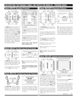 2
2

