Panasonic 72 Service Manual - Page 57
Line Processing of Antenna Cable of Main Unit
 |
UPC - 092281808376
View all Panasonic 72 manuals
Add to My Manuals
Save this manual to your list of manuals |
Page 57 highlights
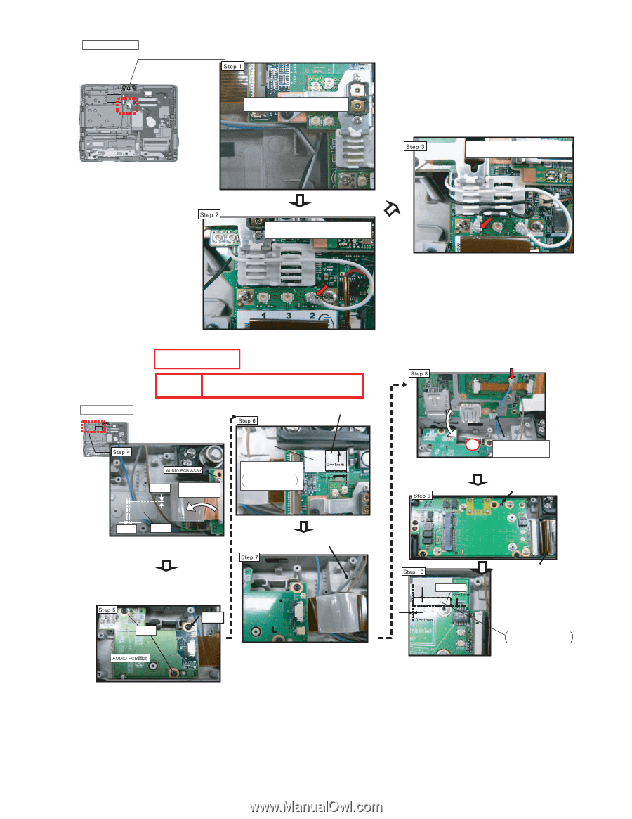
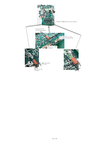
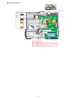
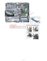
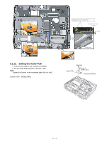
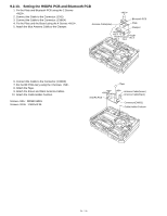
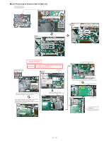
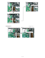
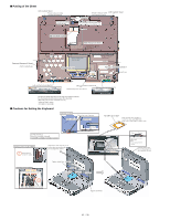
■ Line Processing of Antenna Cable of Main Unit Cable Process 1/3 Place brown/blue/gray cables at left and white/black cables downward. After connecting the white antenna cable, connect it into the Holder as illustrated. After connecting the black antenna cable, connect it into the Holder as illustrated. Cable Process 2/3 Safety Working CAUTION S1:Insulation S2:Pinching Cables S3:Sharp Edge S4:Part No. Check S5:Others Attach side 0-2mm Insert the FPC, Lock Check SHEET Remove the release paper and attach it. To prevent from the cable damaged by screw head. 2-5mm TAPE After processing the cables, inserting the FPC and locking, incline the Audio PCB into the arrow direction. After confirming the cable is not under the AUDIO PCB (processed at the Step 4), tighten the Screws. Because there is a possibility that the cable is scissored between PCB and the both. Screw Screw Process the grey cable to the same direction with the brown cable Connect the blue antenna cable. S2 Insert it into the right notch of the Clamper. If the fixing is not incorrected, there is possibility that the cable is scissored between the PCB and the both. Check the blue cable from the hole. SHEET Attach side Connect the FPC Remove the Release Paper and attach it. To prevent from the cable damage by screw bead.
-
 1
1 -
2
-
3
-
4
-
5
-
6
-
7
-
8
-
9
-
10
-
11
-
12
-
13
-
14
-
15
-
16
-
17
-
18
-
19
-
20
-
21
-
22
-
23
-
24
-
25
-
26
-
27
-
28
-
29
-
30
-
31
-
32
-
33
-
34
-
35
-
36
-
37
-
38
-
39
-
40
-
41
-
42
-
43
-
44
-
45
-
46
-
47
-
48
-
49
-
50
-
51
-
 52
52 -
 53
53 -
 54
54 -
 55
55 -
 56
56 -
 57
57 -
 58
58 -
 59
59 -
 60
60 -
 61
61 -
 62
62 -
63
-
64
-
65
-
66
-
67
-
68
-
69
-
70
-
71
-
72
-
73
-
74
-
75
-
76
-
77
-
78
-
79
-
80
-
81
-
82
-
83
-
84
-
85
-
86
-
87
-
88
-
89
-
90
 |
 |