Panasonic AG-HMX100 Mixers Switchers Catalogue - Page 18
Specifications
 |
View all Panasonic AG-HMX100 manuals
Add to My Manuals
Save this manual to your list of manuals |
Page 18 highlights
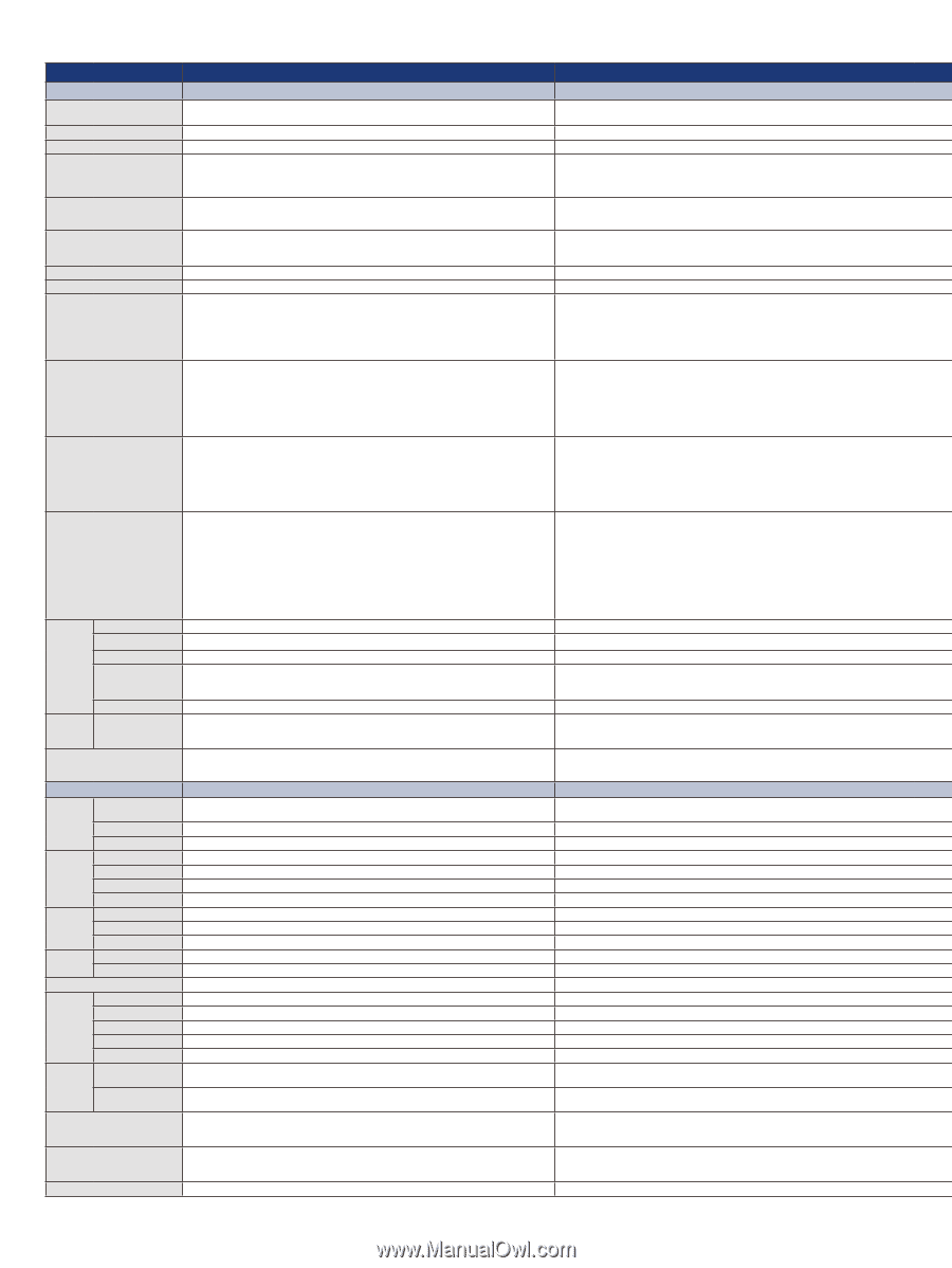
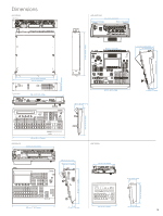
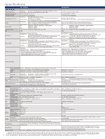
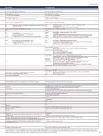
Specifications Specifications Power Requirement Operating Temperature Operating Humidity Dimensions (W x H x D) Weight Video Format Video Processing ME Video Input*3 Video Output*3 Reference Input/Output AV-HS450 AV-HS410 Mainframe: AC 100 V to 120 V(N)/AC 220 V to 240 V(E), 50 Hz/60 Hz, 120 W Control Panel: DC12 V ±10 % (AC adapter provided), 0.8 A 0 °C to 40 °C (32 °F to 104 °F) 10 % to 90 % (no condensation) Mainframe: Control Panel: Mainframe: Control Panel: HD: SD: (2RU) 482 mm x 88 mm x 471 mm (19 inches x 3-7/16 inches x 18-9/16 inches) (excluding protrusions) 560 mm x 88 mm x 299 mm (22-1/16 inches x 3-7/16 inches x 11-3/4 inches) (excluding protrusions) Approx. 9.8 kg (21.6 lb) (without options/excluding accessories) Approx. 10.3 kg (22.7 lb) (with full options/excluding accessories) Approx. 3.9 kg (8.6 lb) (excluding accessories) 1080/59.94i, 1080/50i, 1080/24PsF*1, 1080/23.98PsF*1, 720/59.94p, 720/50p 480/59.94i, 576/50i Y:CB:CR 4:2:2, 10 bit (8 bit for FMEM) /RGB 4:4:4, 8 bit 1ME Mainframe, A maximum of 20 inputs Standard SDI: 16 lines, BNC x 16 (IN 1 to 16) HD (SMPTE292M)/SD (SMPTE259M) standard, 0.8 V [p-p] ±10 % (75 Ω) Optional: Maximum of 4 inputs (IN A1, A2, B1, B2)(Up to 2 optional boards may be inserted into the 2 input/output optional slots) Mainframe, A maximum of 10 outputs Standard SDI: 4 lines, BNC x 5 (OUT 1 to 4 x each, 2 output distribution for OUT 1) HD (SMPTE292M)/SD (SMPTE259M) standard, 0.8 V [p-p] ±10 % (75 Ω) Standard DVI-D: 2 lines, DVI-D x 2, (OUT 5, 6) (Analog output signals are not supported) Optional: Maximum of 12 outputs (OUT A1, A2, B1, B2) (Up to 2 optional boards may be inserted into the 2 input/output optional slots) Mainframe GENLOCK mode: Black burst or Tri-level Sync input signals (with loop-through) Internal sync mode: Black burst output signals x 2 • Same field frequencies as those of the system formats supported. • With the 1080/23.98PsF, 1080/24PsF format, only GENLOCK mode supported. • With the 1080/23.98PsF format, black burst with 10F-ID (SMPTE318M standard met) or TRI signals supported. AC 100 V to 240 V, 50 Hz/60 Hz, 88 W 0 °C to 40 °C (32 °F to 104 °F) 10 % to 90 % (no condensation) 440 mm x 158 mm x 361 mm (17-5/16 inches x 6-7/32 inches x 14-7/32 inches) (excluding protrusions) Approx. 6.2 kg (13.669 lb) (without options/excluding accessories) Approx. 6.6 kg (14.550 lb) e (with full options/excluding accessories) HD: 1080/59.94i, 1080/50i, 1080/24PsF*2, 1080/23.98PsF*2, 720/59.94p, 720/50p, SD: 480/59.94i, 576/50i Y:CB:CR 4:2:2, 10 bit (8 bit for video memory) /RGB 4:4:4, 8 bit 1ME A maximum of 13 inputs Standard SDI: 8 lines, BNC x 8 (IN 1 to 8) (Up-convert support with IN 5 to 8) HD (SMPTE292M)/SD (SMPTE259M) standard, 0.8 V [p-p] ±10 % (75 Ω) Standard DVI-D: 1 line, DVI-D x 1 (Analog input signals are not supported) Optional: Maximum of 4 inputs (IN A1, A2, B1, B2) (Up to 2 optional boards may be inserted into the 2 input/output optional slots) A maximum of 10 outputs Standard SDI: 5 lines, BNC x 6 (OUT 1 to 5 x each, 2 output distribution for OUT 1) HD (SMPTE292M)/SD (SMPTE259M) standard, 0.8 V [p-p] ±10 % (75 Ω) Standard DVI-D: 1 line, DVI-D x 1 (Analog output signals are not supported) Optional: Maximum of 4 outputs (OUT A1, A2, B1, B2) (Up to 2 optional boards may be inserted into the 2 input/ output optional slots) GENLOCK mode: Black burst or Tri-level Sync input signals (with loop-through) Internal sync mode: Black burst output signals x 2 • Same field frequencies as those of the system formats supported. • With the 1080/24PsF format, only GENLOCK mode supported. • With the 1080/23.98PsF format, black burst with 10F-ID (SMPTE318M standard met) or TRI signals supported. Audio Input/Output - - Interface PANEL/MAINFRAME RJ45 x 1, 100 Mbps (to connect between the mainframe and the control panel) EDITOR Mainframe, D-sub 9 pin x 1, RS-422 (GVG protocol compatible) COM Mainframe, D-sub 9 pin x 1, RS-422 (pan-tilt system control) TALLY/GPI Mainframe: D-sub 50 pin x 1 (8 IN, 31 OUT and 1 ALARN OUT may be set) Control Panel: D-sub 25 pin x 1 (8 IN and 8 OUT may be set) LAN Removable Media SD Memory Card Standard Accessories Function Mainframe, RJ45 x 1, 10 BASE-T/100 BASE-TX Supported by the control panel, Capacity: Maximum 32 GB (SDHC Memory Card compatible) Still image file: Loading/saving, setup data: backup CD-ROM (Operating instructions / Image transmission software), AC adapter (for control panel),Power cable (for mainframe and AC adapter), CAT5E cable (STP, straight cable, 10 m (32.8 feet) long) - DD-sub 9 pin x 1, RS-422 D-sub 9 pin x 1, RS-422 D-sub15 pin x 2 (IN 8, OUT 19, ALARM OUT 1) RJ45, 10 BASE-T/100 BASE-TX Capacity: Maximum 32 GB (SDHC Memory Card compatible) Still image file/movie clip file/shot memory/event memory: Loading/saving, Setup data: backup CD-ROM (Operating instructions/DVI input level adjustment file), Power cable (2 m (6.6 feet) long) Wipe/DVE Pattern BKGD Transition Type Image Number of Keys KEYER Key Type Transition Type Wipe/DVE Pattern Number of Keys DSK Key Type Transition Type P in P Number of PinP Transition Type AUX BUS Frame Synchronizer Input Function Freeze Up-Converter Color Corrector Video Processing MultiViewer Output Function Other Function Frame Memory Video Memory Memory Function Wipe x 12, Squeeze x 11, Slide x 8, 3D x 12, 2ch squeeze x 4, 2ch slide x 4, 2ch 3D x 4 Wipe x 16, Squeeze x 16, Slide x 8, 3D x 12 Cut, Mix, Wipe (including DVE) Cut, Mix, Wipe (including DVE) Image effect: PGM/A, PST/B BUS Effect: Mosaic, Defocus, Mono, Paint - 1 1 Linear key, Luminance key, Chroma key, Full key Linear key, Luminance key, Chroma key, Full key*8 Cut, Mix, Wipe (including DVE) Cut, Mix, Wipe (including DVE) Wipe x 12, Squeeze x 11, Slide x 9, 3D x 12 Wipe x 16, Squeeze x 16, Slide x 8, 3D x 12 2 1 Linear key, Luminance key Linear key, Luminance key Mix Mix 2 2 Mix Mix AUX Bus 1 to 4*4 AUX Bus 1 to 4*4 IN 1 to 16*5 IN 1 to 9 (IN 9 is always-on)*5 IN 1 to 16*5 IN 1 to 9*5 IN13 to 16*5 IN5 to 8*5 IN9 to 16 - - IN1 to 8*5 2 systems, Labels, Tally indication, Split-screen (the screen may be split into 4, 9, 10 and 16 sections)*6 1 system, Labels, Tally indication, Split-screen (9 Patterns: 4, 5a/5b, 6a/6b, 9, 10a/10b and 16 sections) OSD (PVW and several MULTI outputs), Phase adjustment, Chroma key sample marker, Down converter (SDI output board only) Phase adjustment, Chroma key sample marker, Down converter (SDI output board only) 4 channels (The data for the images stored in the frame memories can be retained even when the power is turned off by saving it in the flash memory area which is incorporated - inside the unit.) 2 systems: still images and movie clips (The data for the images stored in the frame - memories can be retained even when the power is turned off by saving it in the flash memory*9 area which is incorporated inside the unit.) Shot memory, BKGD/Wipe memory, PinP memory, Camera memory *7, Effect dissolve function Shot memory, Event memory, Effect dissolve function *1: 1080/24PsF and 23.98PsF are not compatible with optional boards AV-HS04 M1, M2, M3, M4, M5, M6, M7, M7D and M8. *2: 1080/24PsF and 23.98PsF are not compatible with optional boards AV-HS04 M1, M2, M3, M4, M5, M6 and M7. *3: For information on input/output signals, see page 10, "Input Formats." *4: AUX BUS 1 is compatible with MIX transition. *5: Specifications for IN A1, 17 A2, B1, and B2 depend on the specs of the mounted optional equipment. *6: Maximum 20 channels may be simultaneously displayed on two screens.
-
 1
1 -
2
-
3
-
4
-
5
-
6
-
7
-
8
-
9
-
10
-
11
-
12
-
 13
13 -
 14
14 -
 15
15 -
 16
16 -
 17
17 -
 18
18 -
 19
19 -
 20
20
 |
 |