Panasonic AV-HS410 Brochure - Page 6
Expanded Functions with Plug-in Software and Optional Boards
 |
View all Panasonic AV-HS410 manuals
Add to My Manuals
Save this manual to your list of manuals |
Page 6 highlights
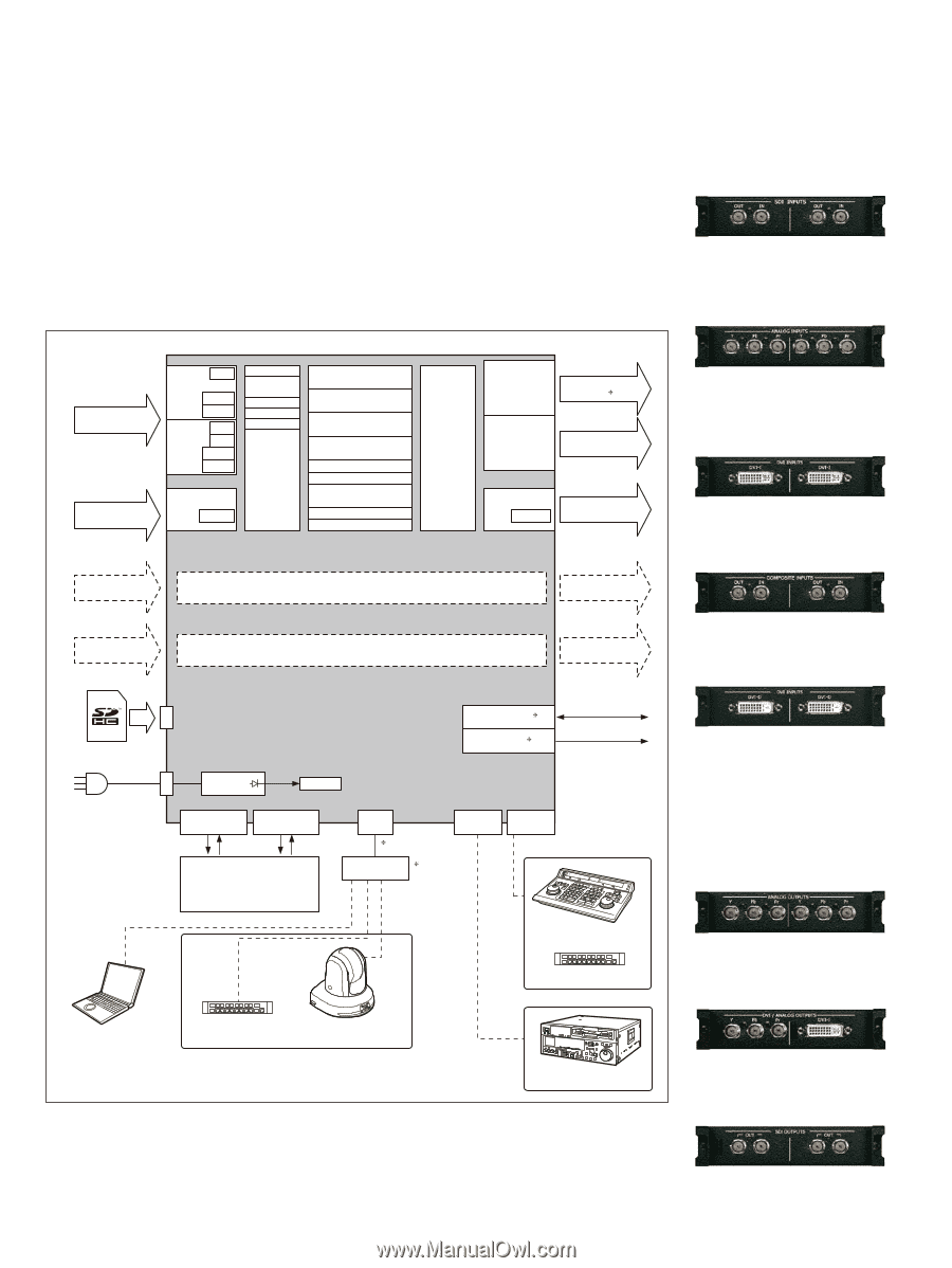
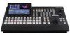
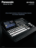
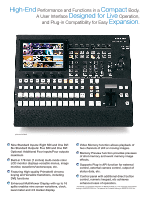
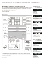
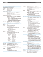
Expanded Functions with Plug-in Software and Optional Boards Plug-in Software Created with a Software Development Kit* Plug-ins allow flexible expansion of software-based functions. A Software Development Kit (SDK) is provided so that third parties or SI enterprises can freely develop the software to add new functions to the AV-HS410. This will enable the system to meet an even wider range of needs, such as controlling the AV-HS410 with an external controller or PC, operating cameras and other devices from the AV-HS410, and outputting status data related to the live switcher or image sources. * Please ask your dealer for details. Block Diagram Input Option Boards (As of December, 2011) AV-HS04M1 SDI Input Board SDI (HD/SD) x 2 (BNC) (Built-in Up-converter) SDI Input 1 to 8 DVI-D Input FS SDI IN 1 to 4 VPrc DbyD FS SDI IN UC 5 to 8 VPrc DbyD DVI-D IN Scaler Black Color BKGD1, 2 ColorBar STILL1, 2 CLIP1, 2 Input matrix BKGD CUT, MIX, WIPE, DVE KEY CUT, MIX, WIPE, DVE PinP1, 2 CUT, MIX DSK CUT, MIX FTB AUX 1 to 4 Multi View WFM MEM PVW SDI OUTPUT 1-1, 1-2 SDI Output 1-1, 1-2 ( 3) Output matrix SDI OUTPUT 2 to 5 SDI Output 2 to 5 DVI-D OUT Scaler DVI-D Output Input A1, A2 Option slot A Output A1, A2 Input B1, B2 Option slot B Output B1, B2 Memory card ~ AC IN AC/DC Power TALLY/GPI 1 TALLY/GPI 2 Dsub 15 Dsub 15 GPI-IN: 8 GPI-OUT: 19 ALARM OUT: 1 GND: 2 LAN RJ45 ( 4) Switching hub ( 5) REF IN/OUT ( 1) REF OUT ( 2) Reference signal COM EDITOR Dsub 9 Dsub 9 Editing controller Aux panel AV-HS04M2 Analog Component Input Board HD/SD Analog Component x 2 (Y/PB/PR) (Built-in Up-converter) AV-HS04M3 DVI Input Board DVI-I x 2 (Built-in Scaler) AV-HS04M6 Analog Composite Input Board Analog Composite x 2 (Built-in Up-converter) AV-HS04M8 Full HD DVI Input Board DVI-D x 2 (compatible with WUXGA) Output Option Boards (As of December, 2011) AV-HS04M4 Analog Output Board HD/SD Analog Component x 2 (Y/PB/PR) Computer Aux panel Remote camera VTR, etc. AV-HS04M5 DVI/Analog Output Board DVI-I×1, HD/SD Analog Component x 1 (Y/PB/PR) *1: When external synchronization is selected as the reference signal setting, the reference signal is input. When internal synchronization is selected, the reference signal is output. *2: When external synchronization is selected as the reference signal setting, the signals are looped through output. When internal synchronization is selected, the reference signal is output. *3: Two sets of the same output signals are distributed from SDI OUTPUT 1. *4: Use a crossover cable when connecting the unit and another device on a 1:1 basis without going through a switching hub. *5: Use a switching hub. AV-HS04M7 SDI Output Board SDI (HD/SD) x 2 (Each one has 2 outputs) (BNC) (Built-in Down-converter)
-
 1
1 -
 2
2 -
 3
3 -
 4
4 -
 5
5 -
 6
6 -
 7
7 -
 8
8
 |
 |